
User Manual

TURBO HD
Bullet Camera
User Manual
Thank you for purchasing our product. If there
are any questions, or requests, please do not
hesitate to contact the dealer.
This manual applies to
This manual may contain several technical
incorrect places or printing errors, and the
content is subject to change without notice.
The updates will be added to the new version of
this manual. We will readily improve or update
the products or procedures described in the
manual.
Regulatory Information
FCC Information
FCC compliance: This equipment has been
tested and found to comply with the limits for a
digital device, pursuant to part 15 of the FCC
Rules. These limits are designed to provide
reasonable protection against harmful
interference when the equipment is operated in
a commercial environment. This equipment
generates, uses, and can radiate radio
frequency energy and, if not installed and used
in accordance with the instruction manual, may
cause harmful interference to radio
communications. Operation of this equipment in
a residential area is likely to cause harmful
interference in which case the user will be
required to correct the interference at his own
expense.
0100001050303
FCC Conditions
This device complies with part 15 of the FCC
Rules. Operation is subject to the following two
conditions:
1. This device may not cause harmful
interference.
2. This device must accept any interference
received, including interference that may
cause undesired operation.
EU Conformity Statement
upon the purchase of equivalent new equipment,
or dispose of it at designated collection points.
For more information see:
www.recyclethis.info.
2006/66/EC (battery directive):
This product contains a battery that
cannot be disposed of as unsorted
municipal waste in the European
Union.
See the product documentation for specific
battery information. The battery is marked with
this symbol, which may include lettering to
indicate cadmium (Cd), lead (Pb), or mercury (Hg).
For proper recycling, return the battery to your
supplier or to a designated collection point. For
more information see: www.recyclethis.info.
This series of camera adopts new generation
sensor with high sensitivity and advanced circuit
design technology It features high resolution,.
low image distortion and low noise, etc , which.
makes it suitable for surveillance system and
image processing system.
l High performance CMOS sensor and high
resolution bring high-quality image;
l Low illumination;
l OSD menu, parameters are configurable;
l Support auto white balance, auto gain control,
electronic shutter control;
SMART IR mode;
l
l
Unit transmission control;
l Advanced 3-axis design meets different
installation requirements.
1 Introduction
1.1 Product Features
1.2 Overview
UD.6L0201D1813A01
2012/19/EU (WEEE directive):
Products marked with this symbol
cannot be disposed of as unsorted
municipal waste in the European
Union. For proper recycling, return
this product to your local supplier
Please refer to the product specification for
camera parameters and functions.
This product and - if applicable - the
supplied accessories too are marked
with "CE" and comply therefore with
the applicable harmonized European
standards listed under the Low Voltage Directive
2006/95/EC, the EMC Directive 2004/108/EC,
the RoHS Directive 2011/65/EU.
1.2.1 Overview of Type I Camera
1.2.2 Overview of Type Camera
II
1.2.3 Overview of Type CameraIII
2 Installation
Before you start:
l Please make sure that the device in the package
is in good condition and all the assembly parts
are included.
l Make sure that all the related equipment is
power-off during the installation.
l Check the specification of the products for the
installation environment.
l Check whether the power supply is matched
with your power output to avoid damage.
l Please make sure the wall is strong enough to
withstand three times the weight of the camera
and the mounting.
l If the wall is the cement wall, you need to insert
expansion screws before you install the camera.
If the wall is the wooden wall, you can use
self-tapping screw to secure the camera.
l If the product does not function properly,
please contact your dealer or the nearest
service center. Do not disassemble the camera
for repair or maintenance by yourself.
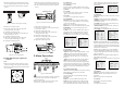
HD Video Cable
Power Cable
Switch Cable
CVBS Cable
Mounting Base
Sun Shield
Lens
IR LED
IR LED
Sun Shield
Adjustable Screw
Mounting Base
Power Cable
HD Video Cable
CVBS Cable
Switch Cable
Lens
Power Cable
Switch Cable
CVBS Cable
HD Video Cable
Sun Shield
Adjustable Screw
IR LED
Steps:
1.Drill the screw holes and the cable hole in the
ceiling according to the supplied drill template.
2.Hammer the supplied plastic expansion bolt into
the screw holes.
2.1 Ceiling Mounting for Type I
Camera
Figure 2-1 Drill Template
III
DS-2CE16D5T-IT5
Type
Model
I
II
III
DS-2CE16C2T-IR
DS-2CE16C2T-IT1
DS-2CE16C2T-IT3
DS-2CE16C2T-IT5
I
II
DS-2CE16D5T-IR
DS-2CE16D5T-IT1
DS-2CE16D5T-IT3
720P
1080P
l All the diagrams only apply to cameras with
a 1080p resolution. The cameras with a 720p
resolution of these three types do not have
CVBS cables and switch cables.
The switch cables are designed for toggling
l
status of the WDR functions for 1080p cameras.
The WDR function is disabled by default, and
you can short the white and black line-ends of
the switch cable to enable the function.
All Screw Holes: for
mounting base
www.hikvision.com
DS-2CE16C2T-IRP