TURBO HD H8T Series Bullet Camera User Manual User Manual Thank you for purchasing our product. If there are any questions, or requests, do not hesitate to contact the dealer. This manual applies to the models below: Type Model Type I Camera DS-2CE16H8T-ITF DS-2CE16H8T-IT1F Type II Camera DS-2CE16H8T-IT3F DS-2CE16H8T-IT5F This manual may contain several technical incorrect places or printing errors, and the content is subject to change without notice.
Regulatory Information FCC Information Please take attention that changes or modification not expressly approved by the party responsible for compliance could void the user’s authority to operate the equipment. FCC compliance: This equipment has been tested and found to comply with the limits for a Class A digital device, pursuant to part 15 of the FCC Rules. These limits are designed to provide reasonable protection against harmful interference when the equipment is operated in a commercial environment.
Safety Instruction These instructions are intended to ensure that user can use the product correctly to avoid danger or property loss. The precaution measure is divided into “Warnings” and “Cautions”. Warnings: Serious injury or death may occur if any of the warnings are neglected. Cautions: Injury or equipment damage may occur if any of the cautions are neglected. Warnings Follow these safeguards to prevent serious injury or death.
Keep the camera away from liquid while in use for non-water-proof device. While in delivery, the camera shall be packed in its original packing, or packing of the same texture.
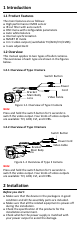
1 Introduction 1.1 Product Features The main features are as follows: High performance CMOS sensor IR cut filter with auto switch OSD menu with configurable parameters Auto white balance Internal synchronization SMART IR mode 4 in 1 video output (switchable TVI/AHD/CVI/CVBS) 3-axis adjustment 1.2 Overview This manual applies to two types of bullet cameras. The overviews of each type are shown in the figures below. 1.2.
Make sure the wall is strong enough to withstand three times the weight of the camera and the bracket. If the wall is cement, insert expansion bolts before installing the camera. If the wall is wooden, use self-tapping screws to secure the camera. If the product does not function properly, contact your dealer or the nearest service center. Do NOT disassemble the camera for repair or maintenance by yourself. 2.1 Installation of Type I Camera 2.1.
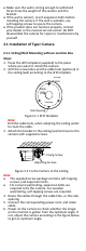
Pan Position [0° to 360°] Rotation Position [0° to 360°] P Screw Tilt Position [0° to 180°] T Screw R Screw Figure 2-3 3-axis Adjustment 1). Loosen the P screw to adjust the pan position [0° to 360°]. Tighten the screw after completing the adjustment. 2). Loosen the T screw to adjust the tilt position [0° to 180°]. Tighten the screw after completing the adjustment. 3). Loosen the R screw and rotate the camera [0° to 360°]. Tighten the screw after completing the adjustment. 2.1.
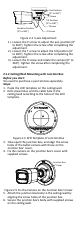
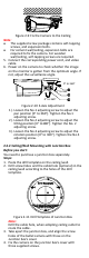
Junction Box Body Figure 2-6 Fix the Junction Box to the Wall/Ceiling 7. Route the cables through the bottom cable hole, or the side cable hole of the junction box. 8. Combine the junction box cover with its body. Figure 2-7 Fix the Junction Box Cover back to its Body 9. Repeat the step 5 and 6 of 2.1.1 Ceiling/Wall Mounting without Junction Box to complete the installation. 2.2 Installation of Type II Camera 2.2.1 Ceiling/Wall Mounting without Junction Box Steps: 1.
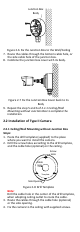
Figure 2-9 Fix the Camera to the Ceiling Note: The supplied screw package contains self-tapping screws, and expansion bolts. For cement wall/ceiling, expansion bolts are required to fix the camera. For wooden wall/ceiling, self-tapping screws are required. 5. Connect the corresponding power cord, and video cable. 6. Power on the camera to check whether the image on the monitor is gotten from the optimum angle. If not, adjust the surveillance angle.
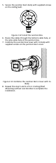
5. Secure the junction box’s body with supplied screws on the ceiling/wall. Figure 2-12 Install the Junction Box 6. Route the cables through the bottom cable hole, or the side cable hole of the junction box. 7. Combine the junction box cover with its body with supplied screws on the junction box’s cover. Figure 2-13 Combine the Junction Box’s Cover with its Body 8. Repeat the step 5 and 6 of 2.2.1 Ceiling/Wall Mounting without Junction Box to complete the installation.
3 Menu Description Purpose: Call the menu by clicking button on the PTZ Control interface, or call preset No.95. Steps: 1. Connect the camera with the TVI DVR, and the monitor, shown as the figure 3-1. TVI DVR Camera Monitor Figure 3-1 Connection 2. Power on the analog camera, TVI DVR, and the monitor to view the image on the monitor. 3. Click PTZ Control to enter the PTZ Control interface. 4. Call the camera menu by clicking button, or call preset No. 95.
1). Click up/down direction button to select the item. 2). Click Iris + to confirm the selection. 3). Click left/right direction button to adjust the value of the selected item. 3.1 VIDOE FORMAT You can set the video format as 5MP@20fps, 4MP@25fps, 4MP@30fps, 2MP@25fps, and 2MP@30fps. Note: When switching the video output as CVBS, you can set the video format as PAL, or NTSC.
3.3 DAY/NIGHT COLOR, BW (Black White), and AUTO are selectable for DAY/NIGHT switch. COLOR The image is colored in day mode all the time. B & W (Black and White) The image is black and white all the time, and the IR LIGHT turns on in the poor light conditions.
Day to Night Threshold is used to control the sensitivity of switching the day mode to the night mode. You can set the value from 1 to 9. The larger the value is, the more sensitive the camera is. Nà D Threshold (Night to Day Threshold) Night to Day Threshold is used to control the sensitivity of switching the night mode to the day mode. You can set the value from 1 to 9. The larger the value is, the more sensitive the camera is 3.
You can set the BRIGHTNESS value from 1 to 9 to darken or brighten the image. The higher the value is, the brighter the image is. CONTRAST This feature enhances the difference in color and light between parts of an image. You can set the CONTRAST value from 1 to 9. SHARPNESS Sharpness determines the amount of detail an imaging system can reproduce. You can set the SHARPNESS value from 1 to 9. SATURATION Adjust this feature to change the saturation of the color. The value ranges from 1 to 9.
PRIVACY MODE AREA 0 AREA 1 AREA 2 AREA 3 COLOR TRANSPARENCY BACK EXIT SAVE & EXIT ON RED OFF Figure 3-9 PRIVACY Select a PRIVACY area. Set the MODE as ON. Click up/down/left/right button to define the position, and the size of the area. 3.6 FACTORY DEFAULT Move the cursor to FACTORY DEFAULT and click Iris+ to reset all the settings to the factory default. 3.7 EXIT Move the cursor to EXIT and click Iris+ to exit the menu without saving. 3.