TURBO HD H1T Series Dome Camera User Manual User Manual Thank you for purchasing our product. If there are any questions, or requests, do not hesitate to contact the dealer. This manual applies to the models below: Type Type I Camera Type II Camera Model DS-2CE56H1T-(A)VPIT3Z(E) DS-2CE56H1T-(A)ITZ(E) This manual may contain technical incorrect places or printing errors, and the content is subject to change without notice. The updates will be added to the new version of this manual.
Regulatory Information FCC Information Please take attention that changes or modification not expressly approved by the party responsible for compliance could void the user’s authority to operate the equipment. FCC compliance: This equipment has been tested and found to comply with the limits for a Class A digital device, pursuant to part 15 of the FCC Rules. These limits are designed to provide reasonable protection against harmful interference when the equipment is operated in a commercial environment.
Safety Instruction These instructions are intended to ensure that user can use the product correctly to avoid danger or property loss. The precaution measure is divided into “Warnings” and “Cautions”. Warnings: Serious injury or death may occur if any of the warnings are neglected. Cautions: Injury or equipment damage may occur if any of the cautions are neglected. Warnings Follow these safeguards to prevent serious injury or death.
Keep the camera away from liquid while in use for non-water-proof device. While in delivery, the camera shall be packed in its original packing, or packing of the same texture.
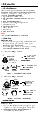
1 Introduction 1.1 Product Features The camera is applicable for both indoor and outdoor conditions, and the application scenarios include road, warehouse, underground parking lot, bar, etc.. The main features are as follows: High performance CMOS sensor Low illumination, 0.01 Lux@(F1.
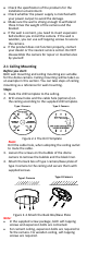
Check the specification of the products for the installation environment. Check whether the power supply is matched with your power output to avoid the damage. Make sure the wall is strong enough to withstand three times the weight of the camera and the bracket. If the wall is cement, you need to insert expansion bolts before you install the camera. If the wall is wooden, you can use self-tapping screws to secure the camera.
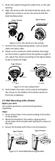
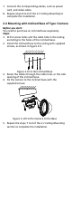
5. Route the cables through the cable hole, or the side opening. 6. Align the camera with the back box/base plate, and tighten the screws to secure the camera with the back box/base plate. Type II Camera Type I Camera Figure 2-3 Fix the camera to the Ceiling 7. Connect the corresponding cables, such as power cable and video cable. 8. Power on the camera to check whether the image on the monitor is gotten from the optimum angle.
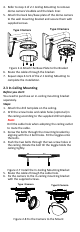
4. Refer to step 3 of 2.1 Ceiling Mounting to remove dome camera’s bubble and the black liner. 5. Attach the back box/base plate of the dome camera to the wall mounting bracket and secure them with supplied screws. Type I Camera Type II Camera Figure 2-6 Attach the Base Plate to the Bracket 6. Route the cables through the bracket. 7. Repeat steps 6 to 9 of the 2.1 Ceiling Mounting to complete the installation. 2.
7. Connect the corresponding cables, such as power cord, and video cable. 8. Repeat steps 8 to 9 of the 2.1 Ceiling Mounting to complete the installation. 2.4 Mounting with Inclined Base of Type I Camera Before you start: You need to purchase an inclined base separately. Steps: 1. Drill 4 screw holes and the cable hole in the ceiling according to the holes of the inclined base. 2. Install the inclined base to the ceiling with supplied screws, as shown in Figure 2-9. Figure 2-9 Fix the Inclined Base 3.
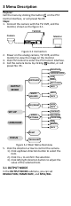
3 Menu Description Purpose: Call the menu by clicking the button on the PTZ Control interface, or call preset No.95. Steps: 1. Connect the camera with the TVI DVR, and the monitor, shown as the figure 3-1. TVI DVR Camera Monitor Figure 3-1 Connection 2. Power on the analog camera, TVI DVR, and the monitor to view the image on the monitor. 3. Click PTZ Control to enter the PTZ Control interface. 4. Call the camera menu by clicking button, or call preset No. 95.
OUTPUT MODE RESOLUTION FRAME RATE NTSC/PAL APPLY BACK 5 MEGA 12.5 FPS PAL Figure 3-3 OUTPUT MODE RESOLUTION Resolution refers to the number of the pixels contained in an image. You can set the resolution as 5 megapixels, 4 megapixels or 1080p. The higher the value, the finer the image is. FRAME RATE Frame rate refers to the number of image output in 1 second. When the resolution is set as 5 megapixels, you are allowed to set the frame rate as 20 fps or 12.5 fps.
EXPOSURE MODE You can set the EXPOSURE MODE as GLOBAL, or BLC. GLOBAL GLOBAL refers to the normal exposure mode which performs exposure according to the whole image brightness. BLC (Backlight Compensation) BLC (Backlight Compensation) compensates light for the front object to make it clear, but this may cause the over-exposure of the background, where the light is strong. When BLC is selected as the exposure mode, the BLC level can be adjusted from 0 to 8.
COLOR The image is colored in day mode all the time. B/W The image is black and white all the time, and the IR LED turns on in the poor light conditions. AUTO Automatically switch COLOR or BW (Black and White) according to actual scene brightness You can turn on/off the INFRARED and set the value of SMART IR in this menu. DAY/NIGHT MODE INFRARED SMART IR BACK AUTO ON 1 Figure 3-6 DAY NIGHT INFRARED You can turn on/off the IR LED to meet the requirements of different circumstances.
DNR (Digital Noise Reduction) The DNR function can decrease the noise effect, especially when capturing moving images in poor light conditions and delivering more accurate and sharp image quality. You can set the DNR value from 1 to 10. MIRROR DEFAULT, H, V, and HV are selectable for mirror. DEFAULT: The mirror function is disabled. H: The image flips 180° horizontally. V: The image flips 180° vertically. HV: The image flips 180° both horizontally and vertically. 3.4.