TURBO HD 4K Series Turret & Dome Camera User Manual User Manual Thank you for purchasing our product. If there are any questions, or requests, do not hesitate to contact the dealer. This manual applies to the models below: Type Model Type II Camera DS-2CE78U8T-IT3 Type III Camera DS-2CE57U8T-VPIT This manual may contain technical incorrect places or printing errors, and the content is subject to change without notice. The updates will be added to the new version of this manual.
Regulatory Information FCC Information Please take attention that changes or modification not expressly approved by the party responsible for compliance could void the user’s authority to operate the equipment. FCC compliance: This equipment has been tested and found to comply with the limits for a Class A digital device, pursuant to part 15 of the FCC Rules. These limits are designed to provide reasonable protection against harmful interference when the equipment is operated in a commercial environment.
Safety Instruction These instructions are intended to ensure that user can use the product correctly to avoid danger or property loss. The precaution measure is divided into “Warnings” and “Cautions”. Warnings: Serious injury or death may occur if any of the warnings are neglected. Cautions: Injury or equipment damage may occur if any of the cautions are neglected. Warnings Follow these safeguards to prevent serious injury or death.
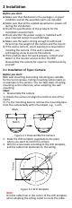
Keep the camera away from liquid while in use for non-water-proof device. While in delivery, the camera shall be packed in its original packing, or packing of the same texture. Mark Description Table 0-1 Mark Description Mark Description DC Voltage 1 Introduction 1.1 Product Features The camera is applicable for both indoor and outdoor conditions, and the application scenarios include road, warehouse, underground parking lot, bar, etc..
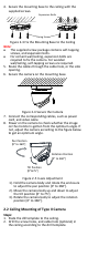
2 Installation Before you start: Make sure that the device in the package is in good condition and all the assembly parts are included. Make sure that all the related equipment is power-off during the installation. Check the specification of the products for the installation environment. Check whether the power supply is matched with your required output to avoid damage. Make sure the wall is strong enough to withstand three times the weight of the camera and the mount.
4. Secure the mounting base to the ceiling with the supplied screws. Expansion Bolts Fixing Screw Figure 2-3 Fix the Mounting Base to the Ceiling Note: The supplied screw package contains self-tapping screws, and expansion bolts. For cement wall/ceiling, expansion bolts are required to fix the camera. For wooden wall/ceiling, self-tapping screws are required. 5. Route the cables through the cable hole, or the side opening. 6. Secure the camera on the mounting base. Figure 2-4 Secure the Camera 7.
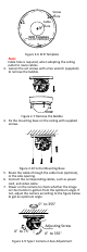
1 1 A Screw Hole Cable Hole Drill Template Hole A: for cables routed through the ceiling screw hole 1: for Mounting Base 1 Figure 2-6 Drill Template Note: Cable hole is required, when adopting the ceiling outlet to route cables. 3. Loosen the set screws with a hex wrench (supplied) to remove the bubble. Figure 2-7 Remove the Bubble 4. Fix the mounting base on the ceiling with supplied screws. Figure 2-8 Fix the Mounting Base 5. Route the cables through the cable hole (optional), or the side opening.
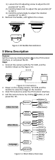
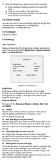
1). Loosen the tilt adjusting screw to adjust the tilt position [0° to 75°]. 2). Hold the black liner to adjust the pan position [0° to 355°]. 3). Hold the camera body to adjust the rotation position [0° to 355°]. 8. Reinstall the bubble, and tighten the screws. Figure 2-10 Bubble Reinstallation 3 Menu Description Purpose: Call the menu by clicking button on the PTZ Control interface, or call preset No.95. Steps: 1. Connect the camera with the TVI DVR, and the monitor shown as the Figure 3-1.
5. Click the direction arrow to control the camera. 1) Click up/down direction button to select the item. 2) Click Iris + to confirm the selection. 3) Click left/right direction button to adjust the value of the selected item. 3.1 Video Format You can set frame rate as 8 MP@12.5fps, 8 MP@15fps, 5 MP@20fps, 4 MP@25fps, 4 MP@30fps, 1080p@25fps, or 1080p@30fps. 3.2 Language Supports English. 3.3 Settings 3.3.
AGC (Automatic Gain Control) It optimizes the clarity of the image in poor light conditions. The AGC level can be set as High, Medium, or Low. Select Off to disable the AGC function. Note: The noise will be amplified when the AGC is on. Slow Shutter Slow Shutter increases the exposure time on a single frame, which makes a camera more sensitive to light. Therefore, it can produce images even under low lux conditions. You can set the Slow Shutter as Off, x2, x4 under 8 MP@15fps, or 8 MP@12.
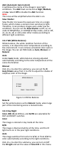
Day Night IR Light Smart IR D à N Threshold N à D Threshold <4> <4> Back Save & Exit Figure 3-5 Day Night IR Light You can turn on/off the IR Light to meet the requirements of different circumstances. Smart IR The Smart IR function is used to adjust the light to its most suitable intensity, and prevent the image from over exposure. You can turn on/off this function.
conditions, and deliver more accurate and sharp image quality. You can set the 3D DNR value from 1 to 10. Mirror Off, H, V, and HV are selectable for mirror. Off: The mirror function is disabled. H: The image flips 180° horizontally. V: The image flips 180° vertically. HV: The image flips 180° both horizontally and vertically.