TURBO HD Full Time Color Series Turret Camera User Manual User Manual Thank you for purchasing our product. If there are any questions, or requests, do not hesitate to contact the dealer. This manual applies to the models below: Model DS-2CE72DFT-F DS-2CE72DFT-F28 This manual may contain technical incorrect places or printing errors, and the content is subject to change without notice. The updates will be added to the new version of this manual.
Regulatory Information FCC Information Please take attention that changes or modification not expressly approved by the party responsible for compliance could void the user’s authority to operate the equipment. FCC compliance: This equipment has been tested and found to comply with the limits for a Class A digital device, pursuant to part 15 of the FCC Rules. These limits are designed to provide reasonable protection against harmful interference when the equipment is operated in a commercial environment.
Safety Instruction These instructions are intended to ensure that user can use the product correctly to avoid danger or property loss. The precaution measure is divided into “Warnings” and “Cautions”. Warnings: Serious injury or death may occur if any of the warnings are neglected. Cautions: Injury or equipment damage may occur if any of the cautions are neglected. Warnings Follow these safeguards to prevent serious injury or death.
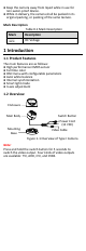
Keep the camera away from liquid while in use for non-water-proof device. While in delivery, the camera shall be packed in its original packing, or packing of the same texture. Mark Description Table 0-1 Mark Description Mark Description DC Voltage 1 Introduction 1.1 Product Features The main features are as follows: High performance CMOS sensor Full time color OSD menu with configurable parameters Auto white balance Internal synchronization Smart light mode 3-axis adjustment 1.
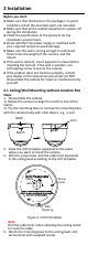
2 Installation Before you start: Make sure that the device in the package is in good condition and all the assembly parts are included. Make sure that all the related equipment is power-off during the installation. Check the specification of the products for the installation environment. Check whether the power supply is matched with your required output to avoid damage. Make sure the wall is strong enough to withstand three times the weight of the camera, and the mount.
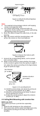
Expansion Bolts Self-tapping Screws Figure 2-2 Attach the Mounting Base to the Ceiling Note: The supplied screw package contains self-tapping screws, and expansion bolts. For cement wall/ceiling, expansion bolts are required to fix the camera. For wooden wall/ceiling, self-tapping screws are required. 5. Route the cables through the cable hole, or the side opening. 6. Align the camera with the mounting base, and secure the camera on the mounting base.
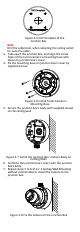
Figure 2-5 Drill Template of the Junction Box Note: Drill the cable hole, when adopting the ceiling outlet to route the cable. 3. Take apart the junction box, and align the screw holes of the turret camera’s mounting base with those on junction box’s cover. 4. Fix the mounting base on junction box’s cover by supplied screws. Figure 2-6 Install Turret Camera’s Mounting Base 5. Secure the junction box’s body with supplied screws on the ceiling/wall.
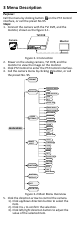
3 Menu Description Purpose: Call the menu by clicking button on the PTZ Control interface, or call the preset No.95. Steps: 1. Connect the camera with the TVI DVR, and the monitor, shown as the figure 3-1. TVI DVR Camera Monitor Figure 3-1 Connection 2. Power on the analog camera, TVI DVR, and the monitor to view the image on the monitor. 3. Click PTZ Control to enter the PTZ Control interface. 4. Call the camera menu by clicking button, or call the preset No. 95.
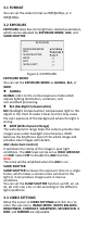
3.1 FORMAT You can set the video format as 2MP@25fps, or 2 MP@30fps. 3.2 EXPOSURE EXPOSURE describes the brightness-related parameters, which can be adjusted by EXPOSURE MODE, AGC, and SLOW SHUTTER. EXPOSURE EXPOSURE MODE AGC SLOW SHUTTER BACK EXIT SAVE & EXIT GLOBAL MEDIUM OFF Figure 3-3 EXPOSURE EXPOSURE MODE You can set the EXPOSURE MODE as GLOBAL, BLC, or WDR. GLOBAL GLOBAL refers to the normal exposure mode which adjusts lighting distribution, variations, and non-standard processing.
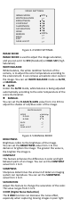
VIDEO SETTINGS IMAGE MODE WHITE BALANCE BRIGHTNESS CONTRAST SHARPNESS SATURATION 3DNR MIRROR BACK EXIT SAVE & EXIT STD 5 5 5 5 5 OFF Figure 3-4 VIDEO SETTINGS IMAGE MODE IMAGE MODE is used to adjust the image saturation, and you can set it to STD (Standard) or HIGH-SAT (High Saturation). WHITE BALANCE White balance, the white rendition function of the camera, is to adjust the color temperature according to the environment. It can remove unrealistic color casts in the image.
conditions, and delivering more accurate and sharper image. You can set the 3 DNR value from 1 to 9. MIRROR OFF, H, V, and HV are selectable for mirror. OFF: The mirror function is disabled. H: The image flips 180° horizontally. V: The image flips 180° vertically. HV: The image flips 180° both horizontally and vertically. 3.4 SMART LIGHT SMART LIGHT is used to control the integrated white light and avoid overexposure when the light is on. You can set the light as AUTO or OFF.
Figure 3-7 PRIVACY Select a PRIVACY area. Set the MODE as ON. Click up/down/left/right button to define the position, and the size of the area. MOTION In the user-defined motion detection surveillance area, the moving object can be detected and the alarm will be triggered. Up to 4 motion detection areas can be configured. MOTION MODE AREA 0 AREA 1 AREA 2 AREA 3 SENSITIVITY COLOR TRANSPARENCY BACK EXIT SAVE & EXIT OFF 50 RED OFF Figure 3-8 MOTION Select a MOTION area.