Network Speed Dome Quick Start Guide
Network Speed Dome·Quick Start Guide Quick Start Guide © 2020 Hangzhou Hikvision Digital Technology Co., Ltd. All rights reserved. This Manual is the property of Hangzhou Hikvision Digital Technology Co., Ltd. or its affiliates (hereinafter referred to as “Hikvision”), and it cannot be reproduced, changed, translated, or distributed, partially or wholly, by any means, without the prior written permission of Hikvision.
Network Speed Dome·Quick Start Guide ABNORMAL OPERATION, PRIVACY LEAKAGE OR OTHER DAMAGES RESULTING FROM CYBER-ATTACK, HACKER ATTACK, VIRUS INSPECTION, OR OTHER INTERNET SECURITY RISKS; HOWEVER, HIKVISION WILL PROVIDE TIMELY TECHNICAL SUPPORT IF REQUIRED. YOU AGREE TO USE THIS PRODUCT IN COMPLIANCE WITH ALL APPLICABLE LAWS, AND YOU ARE SOLELY RESPONSIBLE FOR ENSURING THAT YOUR USE CONFORMS TO THE APPLICABLE LAW.
Network Speed Dome·Quick Start Guide Regulatory Information FCC Information Please take attention that changes or modification not expressly approved by the party responsible for compliance could void the user’s authority to operate the equipment. FCC compliance: This equipment has been tested and found to comply with the limits for a Class A digital device, pursuant to part 15 of the FCC Rules.
Network Speed Dome·Quick Start Guide Safety Instruction These instructions are intended to ensure that user can use the product correctly to avoid danger or property loss. The precaution measure is divided into Warnings and Cautions: Warnings: Neglecting any of the warnings may cause serious injury or death. Cautions: Neglecting any of the cautions may cause injury or equipment damage. Warnings Follow these safeguards to prevent serious injury or death.
Network Speed Dome·Quick Start Guide device is intended for installation in a restricted access location, access can only be gained by service persons or by users who have been instructed about the reasons for the restrictions applied to the location and about any precautions that shall be taken. If the speed dome fails to synchronize local time with that of the network, you need to set up speed dome time manually.
Network Speed Dome·Quick Start Guide Table of Contents 1 Overview ...................................................................................................... 1 1.1 Speed Dome Overview ............................................................................................ 1 1.1.1 Overview of Type I Speed Dome ....................................................................... 1 1.1.2 Overview of Type II Speed Dome ......................................................................
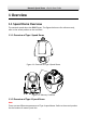
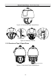
Network Speed Dome·Quick Start Guide 1 Overview 1.1 Speed Dome Overview The network speed dome has EIGHT types. The figures below are for reference only, refer to the actual product as the standard. 1.1.1 Overview of Type I Speed Dome Figure 1-1 Overview of Type I Speed Dome Memory Card Slot Figure 1-2 Memory Card Slot 1.1.2 Overview of Type II Speed Dome Note: There are two different appearances of Type II speed dome. Refer to the actual product for the location of memory card slot.
Network Speed Dome·Quick Start Guide Figure 1-3 Overview of Type II Speed Dome Memory Card Slot Debug Reset Memory Card Slot Figure 1-4 Memory Card Slot 1.1.
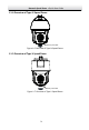
Network Speed Dome·Quick Start Guide 1.1.4 Overview of Type IV Speed Dome Memory Card Slot Figure 1-6 Overview of Type IV Speed Dome 1.1.
Network Speed Dome·Quick Start Guide 1.1.6 Overview of Type VI Speed Dome Memory Card Slot and Reset Button Figure 1-8 Overview of Type VI Speed Dome 1.1.
Network Speed Dome·Quick Start Guide 1.1.8 Overview of Type VIII Speed Dome 线 线 Memory Card Slot and Reset Button Figure 1-10 Overview of Type VIII Speed Dome 1.1.9 Overview of Type IX Speed Dome Memory Card Slot Figure 1-11 Overview of Type IX Speed Dome 1.2 Cable Interfaces The cable interfaces of the speed dome are shown below. The cables are distinguished by different colors. Refer to the labels attached on the cables for identification.
Network Speed Dome·Quick Start Guide Make sure the speed dome is power-off before you connect the cables. Water-proof treatment is required for cable connectors. Refer to Section 2.9 and 2.10 for details. Power Cord RS-485 Cable Audio Cable Alarm Cable Video Cable Network Cable Optical Fiber Figure 1-12 Cable Interfaces 1.3 Alarm Output Alarm output is shown below.
Network Speed Dome·Quick Start Guide 2 Installation Before you start: Check the package contents and make sure that the device in the package is in good condition and all the assembly parts are included. Notes: Do not touch the bubble directly by hand. The image blurs otherwise. Do not power the speed dome up until the installation is finished. To ensure the safety of personnel and equipment, all the installation steps should be done with power supply off.
Network Speed Dome·Quick Start Guide Water-proof treatment is required for cable connectors. Refer to Section 2.9 and 2.10 for details. Steps: 1. Loosen the two lock screws on both sides of the speed dome. Note: Do not remove the lock screws from the speed dome. Back Box Lens Cover Bubble Protective Foam Figure 2-2 Remove the Bubble 2. Pull the bubble to separate it from the back box, and remove the protective accessories.
Network Speed Dome·Quick Start Guide Protective Sticker Figure 2-4 Remove the Protective Accessories for Integrated Speed Some 3. If the speed dome supports PoE (Power over Ethernet) function, you can switch the PoE+ and Hi-PoE function for the speed dome. If PoE function is not supported, skip this step. ON 1 2 Figure 2-5 PoE+ and Hi-PoE Switch Note: If you choose Hi-PoE, a Hi-PoE adapter must be connected. The Hi-PoE module connection is shown in Figure 2-6.
Network Speed Dome·Quick Start Guide Connecting Hi-PoE Steps: 1) Connect the Hi-PoE module to the Internet via the DATA IN interface with a network cable. 2) Connect the Hi-PoE module to the speed dome via the DATA & POWER OUT interface with a network cable. 3) Power on the Hi-PoE module. 4. Install the memory card. 5. Align the cuts on the bubble with the lock screws on the back box to reinstall the bubble. Tighten the lock screws. 6. Install the bracket. 1).
Network Speed Dome·Quick Start Guide 4). Loosen the two lock screws on the bracket. 5). Install the speed dome to the bracket. Rotate the speed dome clockwise tightly. 6). Secure the two lock screws with the wrench. Lock Screw Lock Screw Figure 2-9 Install the Speed Dome to the Bracket 8. Remove the protective film on the bubble after the installation is finished. 2.1.2 In-ceiling Mounting Note: In-ceiling mounting is only supported by indoor speed dome models of Type I.
Network Speed Dome·Quick Start Guide Protective Foam Back Box Bubble Protective Sticker Figure 2-10 Remove the Protective Accessories 5. Drill a hole on the ceiling according to the drill template (supplied). Note: ±2 mm of the circle diameter is tolerable. Φ 224 Unit: mm Figure 2-11 Drill a Hole on the Ceiling 6. Connect the cables. 7. Install the speed dome to the ceiling. 1). Loosen the two lock screws on both sides of the back box and make the locks in internal position as shown in Figure 2-12.
Network Speed Dome·Quick Start Guide 2). Push the speed dome into the mounting hole in the ceiling. 3). Tighten the lock screws with the screwdriver and the locks will automatically rotate outwards to secure the in-ceiling bracket to the ceiling. Ceiling Lock Figure 2-13 Install the Back Box 8. Install the flange. 1). Attach the flange to the bubble and align the triangular notch of the trim ring with the arrow label on the in-ceiling bracket. 2).
Network Speed Dome·Quick Start Guide Water-proof treatment is required for cable connectors. Refer to Section 2.9 and 2.10 for details. Steps: 1. The ceiling mounting speed dome is installed with an in-ceiling bracket by default. You need to remove the in-ceiling bracket first before you install the speed dome. 1). Loosen and remove the four screws as shown in Figure 2-15. Figure 2-15 Remove the Screws 2). Remove the in-ceiling bracket as shown in Figure 2-16. Figure 2-16 Remove the Bracket 3).
Network Speed Dome·Quick Start Guide Figure 2-17 Install the bolts 2. Route the cables. The cables of speed dome can be routed either from the top or the side of the back box, as shown in Figure 2-18. For the cables routed from the top of the back box, it is required to drill a cable hole in the ceiling. Figure 2-18 Cabling for Ceiling Mounting 3. Install the speed dome. 1). Rotate the bubble counterclockwise to separate it from the back box. 2).
Network Speed Dome·Quick Start Guide Screw Holes Cable Hole Figure 2-19 Secure the Mounting Base 7). Route the cables for the speed dome. Align the bottom of the speed dome with the mounting base. 8). Line up the direction of arrow with the spring end of the mounting base. 9). Push the speed dome upwards and then forwards in the direction of the arrow. When the speed dome is placed in position, the spring will automatically snap into the lock clip firmly as shown in Figure 2-20.
Network Speed Dome·Quick Start Guide For wooden wall, you can just use the self-tapping screw to fix the bracket. Make sure that the wall is strong enough to withstand more than eight times the weight of the speed dome and the accessories. The bracket shown in installation is the recommended bracket for this series of speed dome, and a pendent adapter is required if any other bracket is selected. The 1 dimension of pendant adapter is G12 . Water-proof treatment is required for cable connectors.
Network Speed Dome·Quick Start Guide Debug Reset Memory Card Slot Open Cover Memory Card Slot Figure 2-23 Install the Memory Card. 4. Align the cuts on the bubble with the lock screws on the back box to reinstall the bubble. Tighten the lock screws. 5. Refer to steps 6 in section 2.1.1 Wall Mounting to install the bracket. 6. Install the speed dome to the bracket. 1). Hook the back box of the speed dome to the bracket with the safety rope. Route the cables through the bracket. 2).
Network Speed Dome·Quick Start Guide Lock Screw Figure 2-25 Install the Speed Dome to the Bracket 7. Remove the protective film on the bubble after the installation is finished. 2.3 Installing Type III Speed Dome Wall Mounting Notes: For cement wall, you need to use the expansion screw to fix the bracket. The mounting hole of the expansion pipe on the wall should align with the mounting hole on the bracket. For wooden wall, you can just use the self-tapping screw to fix the bracket.
Network Speed Dome·Quick Start Guide Protective Sticker Figure 2-26 Remove Protective Sticker 2. Remove the cover on the back of speed dome as shown in Figure 2-27. Insert the memory card to the memory card slot and install the cover back. SD CARD Memory Card Slot Figure 2-27 Memory Card Slot 3. Refer to steps 6 in section 2.1.1 Wall Mounting to install the bracket. 4. Hook the two ends of the safety rope to the speed dome back box and the bracket respectively. Route the cables through the bracket.
Network Speed Dome·Quick Start Guide Safety Rope Figure 2-28 Install the Safety Rope 5. Loosen the lock screws on the bracket. 6. Align the speed dome with bracket and rotate it counterclockwise or clockwise to the bracket tightly as shown in Figure 2-29. Figure 2-29 Install the Speed dome 7. Use the wrench to tighten the lock screws to secure the speed dome and the bracket.
Network Speed Dome·Quick Start Guide Figure 2-30 Secure the Speed dome 8. Remove the protective film on the bubble after the installation is finished. 2.4 Installing Type IV Speed Dome Wall Mounting Notes: For cement wall, you need to use the expansion screw to fix the bracket. The mounting hole of the expansion pipe on the wall should align with the mounting hole on the bracket. For wooden wall, you can just use the self-tapping screw to fix the bracket.
Network Speed Dome·Quick Start Guide Protective Sticker Figure 2-31 Remove Protective Sticker 2. Remove the cover on the back of speed dome as shown in Figure 2-32. Insert the memory card to the memory card slot and install the cover back. Memory Card Slot Figure 2-32 Memory Card Slot 3. Secure the bracket with four hex nuts and washers. Figure 2-33 Secure the Bracket 4. Apply thread tape to the thread of the head cover and rotate the head cover to the bracket.
Network Speed Dome·Quick Start Guide Figure 2-34 Secure the Head Cover 5. Buckle the handle to the safety rope. + Figure 2-35 Buckle the Handle 6. Hook the two ends of the safety rope to the speed dome back box and the bracket respectively. 7. Hitch the speed dome onto the head cover with the hook on the back box. Hook Back Box Figure 2-36 Hang the Speed Dome 8. Route and connect cables through the head cover and bracket.
Network Speed Dome·Quick Start Guide Note: Water-proof treatment is required for cable connectors. Refer to Section 2.9 and 2.10 for details. Figure 2-37 Route the Cables 9. Align the speed dome back box with the head cover. Use the wrench to tighten the lock screws to secure the speed dome and the bracket. Lock Screw Figure 2-38 Secure the Speed dome 10. Remove the protective film on the bubble after the installation is finished.
Network Speed Dome·Quick Start Guide 2.5 Installing Type V Speed Dome Wall Mounting Notes: For cement wall, you need to use the expansion screw to fix the bracket. The mounting hole of the expansion pipe on the wall should align with the mounting hole on the bracket. For wooden wall, you can just use the self-tapping screw to fix the bracket. Make sure that the wall is strong enough to withstand more than eight times the weight of the speed dome and the accessories.
Network Speed Dome·Quick Start Guide Memory Card Slot Figure 2-40 Memory Card Slot 3. Secure the bracket with four hex nuts and washers. Figure 2-41 Secure the Bracket 4. Apply thread tape to the thread of the head cover and rotate the head cover to the bracket. Secure the head cover to the bracket with set screws (supplied). Figure 2-42 Secure the Head Cover 5. Buckle the handle to the safety rope.
Network Speed Dome·Quick Start Guide + Figure 2-43 Buckle the Handle 6. Hook the two ends of the safety rope to the speed dome back box and the bracket respectively. 7. Hitch the speed dome onto the head cover with the hook on the back box. Figure 2-44 Hang the Speed Dome 8. Route and connect the cables through the head cover and bracket. Note: Water-proof treatment is required for cable connectors. Refer to Section 2.9 and 2.10 for details.
Network Speed Dome·Quick Start Guide Figure 2-45 Route the Cables 9. Align the speed dome back box with the head cover. Use the wrench to tighten the lock screws to secure the speed dome and the bracket. Lock Screw Figure 2-46 Secure the Speed dome 10. Remove the protective film on the bubble after the installation is finished. 2.
Network Speed Dome·Quick Start Guide Wall mounting bracket Wall mounting bracket + corner mounting bracket Wall mounting bracket + vertical pole mounting bracket Figure 2-47 Brackets for Installation For cement wall, you need to use the expansion screw to fix the bracket. The mounting hole of the expansion pipe on the wall should align with the mounting hole on the bracket. For wooden wall, you can just use the self-tapping screw to fix the bracket.
Network Speed Dome·Quick Start Guide Lock Screw Head Cover Figure 2-49 Fix Head Cover to Bracket 3. Hook the speed dome to the bracket with supplied safety rope. Safety Rope Figure 2-50 Use Safety Rope to Hook the Speed Dome to Bracket 4. Connect the cables. Note: You can pull the cables through the small door on the wall mounting bracket. Unscrew to open it. Water-proof treatment is required for cable connectors. Refer to Section 2.9 and 2.10 for details.
Network Speed Dome·Quick Start Guide Figure 2-51 Door on Bracket 5. Align the speed dome with the head cover. Use the wrench to tighten the lock screws. Lock Screws Figure 2-52 Fix the Speed Dome to Head Cover Pendant Mounting Notes: For cement ceiling, you need to use the expansion screw to fix the bracket. The mounting hole of the expansion pipe on the wall should align with the mounting hole on the bracket. For wooden ceiling, you can just use the self-tapping screw to fix the bracket.
Network Speed Dome·Quick Start Guide Figure 2-54 Fix the Bracket to Ceiling 2. Fix the head cover to the pendant mounting bracket. 1). Apply thread tape to the thread of the head cover and rotate the head cover to the bracket. 2). Tighten the lock screws. Lock Screws Head Cover Figure 2-55 Fix Head Cover to Bracket 3. Hook the speed dome to the bracket with supplied safety rope.
Network Speed Dome·Quick Start Guide 4. Connect the cables. Note: Water-proof treatment is required for cable connectors. Refer to Section 2.9 and 2.10 for details. 5. Align the speed dome with the head cover. Use the wrench to tighten the lock screws. Lock Screws Figure 2-57 Fix the Speed Dome to Head Cover 2.7 Installing Type VIII Speed Dome Wall Mounting Notes: For cement wall, you need to use the expansion screw to fix the bracket.
Network Speed Dome·Quick Start Guide Figure 2-58 Install the bracket 2. Use the wrench to fix head cover on the bracket. Figure 2-59 Install head cover 3. Hook the speed dome to the bracket with supplied safety rope. 线 线 Figure 2-60 Use Safety Rope to hook the camera to the bracket 4. Route and connect the cables through the head cover and bracket. Note: Water-proof treatment is required for cable connectors. Refer to Section 2.9 and 2.10 for details.
Network Speed Dome·Quick Start Guide Figure 2-61 Connect the cables 5. Align the speed dome with the head cover. Use the wrench to tighten the lock screws. Lock Screws Figure 2-62 Secure the speed dome Horizontal Pole Mounting Before you start: Prepare one bracket and three hoops, and fix the hoops on the bracket.
Network Speed Dome·Quick Start Guide Figure 2-63 Prepare accessory Steps: 1. Lock the hoops and bracket on a horizontal pole, and route the cables through the vertical mounting bracket. Then fix the vertical mounting bracket on the bracket attached on the pole before. Figure 2-64 Route the cables 2. Use the wrench to fix the head cover on the bracket.
Network Speed Dome·Quick Start Guide 3. Hook the speed dome to the bracket with supplied safety rope. Safety Rope Hook 线 线 Figure 2-66 Use safe rope to hook the camera with bracket 4. Connect the cables, and align the speed dome with the head cover, using wrench to tighten the screws on the head cover. Figure 2-67 Finish the installation Vertical Pole Mounting Before you start: Prepare one bracket and three hoops, and fix the hoops on the bracket.
Network Speed Dome·Quick Start Guide Figure 2-68 Prepare accessory Steps: 1. Lock the hoops and bracket on a vertical pole, and route the cables through the vertical mounting bracket. Then fix the vertical mounting bracket on the bracket attached on the pole before. Figure 2-69 Route the cables 2. Use the wrench to fix the head cover on the bracket. Figure 2-70 Fix the head cover 3. Hook the speed dome to the bracket with supplied safety rope.
Network Speed Dome·Quick Start Guide 线 线 Figure 2-71 Use safe rope to hook the camera with bracket 4. Connect the cables, and align the speed dome with the head cover, using wrench to tighten the screws on the head cover. Figure 2-72 Finish the installation Pendant Mounting Steps: 1. Drill four holes on the ceiling to match those on the pendant mount bracket.
Network Speed Dome·Quick Start Guide 2. Route the cables through the bracket, then align the base plate to the holes and fix it to the ceiling with four screws. Figure 2-74 Route the cables and fix the bracket on the ceiling 3. Use the wrench to fix the head cover on the bracket. Figure 2-75 Fix the head cover 4. Hook the speed dome to the bracket with supplied safety rope.
Network Speed Dome·Quick Start Guide 5. Connect the cables, and align the speed dome with the head cover, using wrench to tighten the screws on the head cover. Figure 2-77 Finish the installation 2.8 Installing Type IX Speed Dome Wall Mounting Notes: You can use a wall mounting bracket alone, or you can use a wall mounting bracket together with a corner mounting bracket or a vertical pole mounting bracket to fix the speed dome at a corner or on a pole. The brackets are not included.
Network Speed Dome·Quick Start Guide Make sure that the wall is strong enough to withstand more than eight times the weight of the speed dome and the accessories. If you use the brackets the dealer recommends, the pendant adapter in the package is not needed during installation. The included pendent adapter might be useful if 1 you use other brackets. The dimension of pendant adapter is G12 . Figure 2-79 Supplied Pendant Adapter Steps: 1. Refer to steps 6 in section 2.1.
Network Speed Dome·Quick Start Guide Steps: 1.Feed the network cable through ① and ③ in order. 2.Fix ② on the network cable between ① and ③. 3.Place ⑤ onto the end of ⑥, and plug the RJ45 male connector into RJ45 female connector. 4.Screw ③ to ⑥ clockwise. 5.Push ② into ③. 6.Secure ① with the ③ in clockwise direction. 2.
Network Speed Dome·Quick Start Guide Cable Connector Figure 2-82 Wrap the Water-proof Tape Note: Make sure that all naked wires are all firmly wrapped in the water-proof tape. 4. Press the tape on both ends of the connector to make sure no water can get in as the figure below. Press s es Pr ss Pre Press Figure 2-83 Press the Water-proof Tape 5. Wrap the water-proof tape around the remaining unused cables tightly as the figure below.
Network Speed Dome·Quick Start Guide Note: Make sure that all naked wires are all firmly wrapped in the water-proof tape. 6. Press the tape to make sure no water can get in as the figure below. Press s es Pr ss Pre Press Figure 2-85 Press the Water-proof Tape 2.11 Protective Measures for Outdoor Installation If the device is installed outdoors, necessary protective measures should be taken to ensure safety. Scan the following QR code to get protective measures for outdoor installation.
Network Speed Dome·Quick Start Guide 3 Activate and Access Network Camera Scan the QR code to get Activate and Visit Network Camera. Note that mobile data charges may apply if Wi-Fi is unavailable.
Network Speed Dome·Quick Start Guide 48 UD19618B