PanoVu Series Camera Quick Start Guide UD01546B
PanoVu Series Camera·Quick Start Guide Quick Start Guide COPYRIGHT © 2016 Hangzhou Hikvision Digital Technology Co., Ltd. ALL RIGHTS RESERVED. Any and all information, including, among others, wordings, pictures, graphs are the properties of Hangzhou Hikvision Digital Technology Co., Ltd. or its subsidiaries (hereinafter referred to be “Hikvision”).
PanoVu Series Camera·Quick Start Guide Regulatory Information FCC Information FCC compliance: This equipment has been tested and found to comply with the limits for a Class A digital device, pursuant to part 15 of the FCC Rules. These limits are designed to provide reasonable protection against harmful interference when the equipment is operated in a commercial environment.
PanoVu Series Camera·Quick Start Guide Safety Instruction These instructions are intended to ensure that user can use the product correctly to avoid danger or property loss. The precaution measure is divided into Warnings and Cautions: Warnings: Neglecting any of the warnings may cause serious injury or death. Cautions: Neglecting any of the cautions may cause injury or equipment damage. Warnings Follow these safeguards to prevent serious injury or death.
PanoVu Series Camera·Quick Start Guide Exposing the equipment to direct sun light, low ventilation or heat source such as heater or radiator is forbidden (ignorance can cause fire danger). Do not aim the panoVu camera at the sun or extra bright places. A blooming or smear may occur otherwise (which is not a malfunction however), and affecting the endurance of sensor at the same time.
PanoVu Series Camera·Quick Start Guide Table of Contents 1 Installation ................................................................................................... 6 1.1 Connecting Cables .................................................................................................................... 6 1.2 Alarm Input and Output Connection ........................................................................................ 7 2 Mounting Application ...........................................
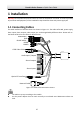
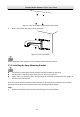
PanoVu Series Camera·Quick Start Guide 1 Installation Warning: Do not power the panoVu camera up until the installation is finished. To ensure the safety of personnel and equipment, all the installation steps should be done with power supply off. 1.1 Connecting Cables The cable interfaces of PanoVu camera are shown in Figure 1-1. The cables of RS-485, power supply, alarm inputs, alarm outputs, video output, etc. are distinguished by different colors.
PanoVu Series Camera·Quick Start Guide 1.
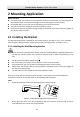
PanoVu Series Camera·Quick Start Guide 2 Mounting Application Before you start: For cement wall, you need to use the expansion screw to fix the bracket. The mounting hole of the expansion pipe on the wall should align with the mounting hole on the bracket. For wooden wall, you can just use the self-tapping screw to fix the bracket. The wall must be thick enough to install the expansion screws.
PanoVu Series Camera·Quick Start Guide Figure 1-4 Drill Screw Hole and Insert Expansion Screw 3. Secure the bracket with 4 hex nuts and washers. Figure 1-5 Drill Screw Holes Please take water-proof measures when installing outdoor PanoVu Camera. 2.1.2 Installing the Hoop Mounting Bracket The pole for mounting the PanoVu Camera should be suitable for the hoop. The diameter of the hoop ranges from 67mm to 127mm (2.64’ to 5’).
PanoVu Series Camera·Quick Start Guide Pendent Bracket Hoop Bracket Figure 1-6 Hoop Bracket and Pendent Bracket 2. Fix the hoop to the pole by adjusting the hoop according to the pole, as shown in Figure 1-7. Fixing Plate Towards the Ground Figure 1-7 Drill Hole and Insert Expansion Screws 3. Fix the hoop bracket with the pendent bracket. 1) Route the cables through the pendent mounting bracket.
PanoVu Series Camera·Quick Start Guide 2.2 Installing the PanoVu Camera The appearance of PanoVu camera may vary according to the models. The appearance shown below is only for reference. 2.2.1 Installing the 180° Panoramic + PTZ Camera Steps: 1. Loosen the two lock screws on the both side of the camera. Pull the lower camera to separate it from the back box as shown in Figure 1-9. Please do not remove the lock screws from the camera.
PanoVu Series Camera·Quick Start Guide Figure 1-11 Micro SD Card Slot 4. Separate the head cover from the camera main body, as shown in Figure 1-12. Head Cover Camera Main Body Figure 1-12 Head Cover of PanoVu Camera 5. 1) 2) 3) 4) Install the head cover of PanoVu camera. Loosen the two lock screws and make sure that the screws do not appear in the inner side of bracket, as shown in Figure 1-13. Route the cables through the head cover and insert the head cover into the bottom of the bracket.
PanoVu Series Camera·Quick Start Guide Safety Rope VIDEO Figure 1-14 Install the Safety Rope 7. 8. Connect all cables and insert the rest cables into the bracket. Fix the PanoVu camera with the head cover by fixing screws of the head cover and bracket, as shown in Figure 1-15. Figure 1-15 Fix the PanoVu Camera 2.2.2 Installing the 360° Panoramic + PTZ Camera Steps: 1. Loosen the two lock screws on the both side of the camera.
PanoVu Series Camera·Quick Start Guide Back Box Lens Cover Lower Dome Protective Foam Figure 1-16 Remove the Lower Camera 2. Remove the protective foam, sticker and lens cover from the camera drive. As shown in Figure 1-17. Sticker Figure 1-17 Remove the Sticker 3. Install the micro SD card. The Micro SD card slot of network camera is shown in Figure 1-18. Insert the matched micro SD card until the card slot clicks. Figure 1-18 Micro SD Card Slot 4.
PanoVu Series Camera·Quick Start Guide Head Cover Camera Main Body Figure 1-19 Head Cover of PanoVu Camera 5. Install the head cover of PanoVu camera. 1) Loosen the two lock screws and make sure that the screws do not appear in the inner side of bracket, as shown in Figure 1-20. 2) Route the cables through the head cover and insert the head cover into the bottom of the bracket. 3) Fix the head cover with the bracket by rotating the head cover clockwise or anticlockwise.
PanoVu Series Camera·Quick Start Guide 7. 8. Connect all cables and insert the rest cables into the bracket. Fix the PanoVu camera with the head cover by fixing screws of the head cover and bracket, as shown in Figure 1-22. Figure 1-22 Fix the PanoVu Camera 2.2.3 Installing the 360° Panoramic Camera Steps: 1. Get the camera from the package, as shown in Figure 1-23. VIE DO Figure 1-23 7+1 PanoVu Camera 2. Install the micro SD card.
PanoVu Series Camera·Quick Start Guide 2) Insert the matched micro SD card until the card slot clicks. 3) Put the cover back on the camera. 3. Install the head cover of PanoVu camera. 1) Loosen the two lock screws and make sure that the screws do not appear in the inner side of bracket, as shown in Figure 1-25. 2) Route the cables through the head cover and insert the head cover into the bottom of the bracket. 3) Fix the head cover with the bracket by rotating the head cover clockwise or anticlockwise.
PanoVu Series Camera·Quick Start Guide Figure 1-27 Fix the PanoVu Camera 18
PanoVu Series Camera·Quick Start Guide 3 Setting the Camera Over the LAN You shall acknowledge that the use of the product with Internet access might be under network security risks. For avoidance of any network attacks and information leakage, please strengthen your own protection. If the product does not work properly, please contact with your dealer or the nearest service center. 3.
PanoVu Series Camera·Quick Start Guide The default IP address of the panoVu camera is 192.168.1.64. Figure 3-2 Activation Interface(Web) 3. Create a password and input the password into the password field. STRONG PASSWORD RECOMMENDED–We highly recommend you create a strong password of your own choosing (Using a minimum of 8 characters, including at least three of the following categories: upper case letters, lower case letters, numbers, and special characters.
PanoVu Series Camera·Quick Start Guide Figure 3-3 SADP Interface 3. Create a password and input the password in the password field, and confirm the password. STRONG PASSWORD RECOMMENDED–We highly recommend you create a strong password of your own choosing (Using a minimum of 8 characters, including at least three of the following categories: upper case letters, lower case letters, numbers, and special characters.) in order to increase the security of your product.
PanoVu Series Camera·Quick Start Guide 3. Change the device IP address to the same subnet with your computer by either modifying the IP address manually or checking the checkbox of Enable DHCP. Figure 3-4 Modify the IP Address 4. Input the password and click Save to activate your IP address modification.
PanoVu Series Camera·Quick Start Guide 4 Accessing via Web browser System Requirement: Operating System: Microsoft Windows XP SP1 and above version / Vista / Win7 / Server 2003 / Server 2008 32bits CPU: Intel Pentium IV 3.0 GHz or higher RAM: 1G or higher Display: 1024×768 resolution or higher Web Browser: Internet Explorer 8.0 and above version, Apple Safari 5.02 and above version, Mozilla Firefox 5 and above version and Google Chrome18 and above version Steps: 1. Open the web browser. 2.
PanoVu Series Camera·Quick Start Guide Figure 4-2 Download Plug-in Figure 4-3 Install Plug-in 6. Reopen the web browser after the installation of the plug-in and repeat the above steps 2-4 to login. For detailed instructions of further configuration, please refer to the user manual of network panoVu camera.
PanoVu Series Camera·Quick Start Guide 25