Network Positioning System Quick Start Guide
Network Positioning System·Quick Start Guide Quick Start Guide COPYRIGHT © 2018 Hangzhou Hikvision Digital Technology Co., Ltd. ALL RIGHTS RESERVED. Any and all information, including, among others, wordings, pictures, graphs are the properties of Hangzhou Hikvision Digital Technology Co., Ltd. or its subsidiaries (hereinafter referred to be “Hikvision”).
Network Positioning System·Quick Start Guide ABNORMAL OPERATION, PRIVACY LEAKAGE OR OTHER DAMAGES RESULTING FROM CYBER ATTACK, HACKER ATTACK, VIRUS INSPECTION, OR OTHER INTERNET SECURITY RISKS; HOWEVER, HIKVISION WILL PROVIDE TIMELY TECHNICAL SUPPORT IF REQUIRED. SURVEILLANCE LAWS VARY BY JURISDICTION. PLEASE CHECK ALL RELEVANT LAWS IN YOUR JURISDICTION BEFORE USING THIS PRODUCT IN ORDER TO ENSURE THAT YOUR USE CONFORMS THE APPLICABLE LAW.
Network Positioning System·Quick Start Guide Regulatory Information FCC Information Please take attention that changes or modification not expressly approved by the party responsible for compliance could void the user’s authority to operate the equipment. FCC compliance: This equipment has been tested and found to comply with the limits for a Class A digital device, pursuant to part 15 of the FCC Rules.
Network Positioning System·Quick Start Guide Safety Instruction These instructions are intended to ensure that user can use the product correctly to avoid danger or property loss. The precaution measure is divided into Warnings and Cautions: Warnings: Neglecting any of the warnings may cause serious injury or death. Cautions: Neglecting any of the cautions may cause injury or equipment damage. Warnings Follow these safeguards to prevent serious injury or death.
Network Positioning System·Quick Start Guide The sensor may be burned out by a laser beam, so when any laser equipment is being used, make sure that the surface of the sensor not be exposed to the laser beam. For working temperature, refer to the specification manual for details. To avoid heat accumulation, good ventilation is required for a proper operating environment. While shipping, the product should be packed in its original packing. Use the provided glove when open up the product cover.
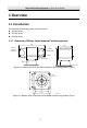
Network Positioning System·Quick Start Guide Table of Contents 1 Overview ...................................................................................................... 7 1.1 Introduction ........................................................................................................ 7 1.1.1 Overview of DY5xxx Series Network Positioning System ............................. 7 1.1.2 Overview of DY7xxx Series Network Positioning System ............................. 8 1.1.
Network Positioning System·Quick Start Guide 1 Overview 1.1 Introduction The network positioning system has three series: DY5xxx Series DY7xxx Series DY9xxx Series 1.1.
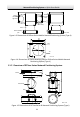
Network Positioning System·Quick Start Guide 306 165 Wiper 212 Shield (Camera Side) Shield (Auxiliary Light Side) Main body Base 35 Shock-absorbing pad Unit: mm Figure 1-3 Dimensions of DY5xxx Series Mobile Network Positioning System (Type II) 175 140 175 140 4-Φ9 134 Unit: mm Figure 1-4 Dimensions of Shock-absorbing Pad for DY5xxx Series Mobile Network Positioning System (Type II) 1.1.2 Overview of DY7xxx Series Network Positioning System 188 396 Shield 377.
Network Positioning System·Quick Start Guide 396 188 Shield IR Main Body 377.5 218 Wiper Base Unit: mm Figure 1-6 Dimensions of DY7xxx Series IR Network Positioning System (Type I with Wiper) 188 396 377.
Network Positioning System·Quick Start Guide 1.1.
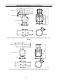
Network Positioning System·Quick Start Guide 334 256 505 Shield Wiper Main Body Base Unit: mm 180 116.7 Figure 1-11 Dimension of DY9xxx Series Laser Network Positioning System (Type IV) Φ165 Φ180 4-Φ9 116.7 Unit:mm Figure 1-12 Bottom View of DY9xxx Series Network Positioning System 1.2 Cable Descriptions Cables of network positioning system are shown in Figure 1-13. The cables are distinguished by different colors. Refer to the labels attached on the cables for identification.
Network Positioning System·Quick Start Guide Power Cord RS-485 Cable Alarm Cable Audio Cable Video Cable Network Cable Figure 1-13 Cables 1.3 Alarm Input/Output Network positioning system can be connected with alarm input (0 to 5 VDC) and alarm output as shown in Figure 1-14. The alarm provides the relay output (no voltage), and the external power supply is required when it connects to the alarm device.
Network Positioning System·Quick Start Guide 2 Installation Before you start: Check the package contents and make sure that the device in the package is in good condition and all the assembly parts are included. Notes: Do not power the positioning system up until the installation is finished. To ensure safety of personnel and equipment, all the installation steps should be done with power supply off.
Network Positioning System·Quick Start Guide Figure 2-2 Fix the Positioning System (Type IV) Note: The thickness of the pedestal steel plate should be more than 5 mm. 2) Connect the corresponding cables. 2. Adjust the laser. 1) Observe the location of laser spot in the image. Adjust the zoom ratio of the lens to a large value, the laser supplementary lighting system will adjust the light according to the zoom ratio, and then you can see the laser spot on the live view image.
Network Positioning System·Quick Start Guide Inner Hexagon Screw Inner Hexagon Screw Figure 2-4 Open the Lid of Housing (Type III) For type IV camera, loosen the screws of sunshield and top cover. Take down the sunshield and top cover. M4 Cross Screw Sunshield Top Cover M4 Torx Needle Screw Figure 2-5 Open the Sunshield of Housing (Type IV) 3) Insert the memory card into the memory card slot.
Network Positioning System·Quick Start Guide Memory Card Figure 2-6 Insert the Memory Card (Type III) Memory Card Memory Card DarkFighterX Figure 2-7 Insert the Memory Card (Type IV) 4) Slightly adjust the control screws for the laser according to the actual situation.
Network Positioning System·Quick Start Guide Eccentric Wheel Tilting Adjustment Screw Panning Fastening Screw Figure 2-9 Adjust the Laser (Type IV) Notes: Panning Adjustment: Loosen the two panning fastening screws, rotate the eccentric wheel to adjust the laser spot in the horizontal direction, and fasten the screws after adjusting. Tilt Adjustment: Tighten or loosen the tilting adjustment screw to adjust the position of the laser spot in the vertical direction. 3.
Network Positioning System·Quick Start Guide Figure 2-11 Restore the Housing (Type IV) 4. Connect the corresponding cables and turn the power on; the system will do the self-test automatically. 2.1.2 Installing DY9xxx Series IR Network Positioning System (Type II) Steps: 1. Install the IR module. 1) Align the screw holes on the IR bracket with the screw holes on the housing as shown in Figure 2-12. Insert and tighten the two M4*10 screws to secure the bracket.
Network Positioning System·Quick Start Guide Figure 2-13 Secure the IR Module 3) Align the buckles to the screw holes on the IR bracket and secure them with two M4*10 screws. Note: The buckles are fixed with the cable by default. Figure 2-14 Secure the Cables to IR Bracket 2. Route the cables of IR modules. 1) Pull out the two original plugs from the housing. 2) Loosen the nuts on the water-proof cable plugs. 3) Route the IR module cables through the cable holes on the housing respectively.
Network Positioning System·Quick Start Guide 3. Connect the cables of IR modules. 1) Loosen the toggles from the bolts on the downside of the housing and pull the bolts outward from the housing. 2) Open the lid. Figure 2-16 Open the Housing 3) Connect the cables to the connectors on the housing respectively. Figure 2-17 Connect the Cables 4. Insert the memory card into the memory card slot as shown in Figure 2-18 and Figure 2-19.
Network Positioning System·Quick Start Guide DarkFighterX Memory Card Figure 2-19 Install the Memory Card (DarkFighterX) 5. Restore the housing and tighten the screws for waterproof. 6. Fix the positioning system. Refer to Step 1 Fix the positioning system. in section 2.1.1 Installing DY9xxx Series Laser Network Positioning System (Type III and Type IV). 7. Connect the corresponding cables and turn the power on; the system will do the self-test automatically. 2.1.
Network Positioning System·Quick Start Guide 3 Setting the Positioning System over the LAN Notes: You shall acknowledge that the use of the product with Internet access might be under network security risks. For avoidance of any network attacks and information leakage, strengthen your own protection. If the product does not work properly, contact with your dealer or the nearest service center.
Network Positioning System·Quick Start Guide Activation via web browser, activation via SADP software, and activation via client software are supported. We will take activation via web browser and activation via SADP software as examples to introduce the positioning system activation. Note: For the details of activation via client software, refer to the user manual of the network positioning system. 3.2.1 Activation via Web Browser Steps: 1. Power on the positioning system.
Network Positioning System·Quick Start Guide 3.2.2 Activation via SADP Software SADP software is used for detecting the online device, activating the device, and resetting the password. Get the SADP software from the supplied disk or the official website, and install the SADP software according to the prompts. Follow the steps to activate the positioning system. Steps: 1. Run the SADP software to search the online devices. 2. Check the device status from the device list, and select an inactive device.
Network Positioning System·Quick Start Guide Note: You can check whether the activation is completed on the popup window. If activation failed, make sure that the password meets the requirement and try again. 3.3 Modifying the IP Address Purpose: To view and configure the network positioning system via LAN (Local Area Network), you need to connect the positioning system in the same subnet with your PC.
Network Positioning System·Quick Start Guide Note: You can enable the Hik-Connect service for the device during activation. Refer to section 5.1 Enable Hik-Connect Service on Positioning System. Hik-Connect service is not supported by certain positioning system models. 4. Input the admin password and click Modify to activate your IP address modification. The batch IP address modification is supported by SADP. Refer to the user manual of SADP for details.
Network Positioning System·Quick Start Guide 4 Accessing via Web browser System Requirement: Operating System: Microsoft Windows XP SP1 and above version/Vista/Win7/Server 2003/Server 2008 32bits CPU: Intel Pentium IV 3.0 GHz or higher RAM: 1G or higher Display: 1024×768 resolution or higher Web Browser: Internet Explorer 7.0 and above version, Apple Safari 5.02 and above version, Mozilla Firefox 5 and above version and Google Chrome 8 and above version Steps: 1. Open the web browser. 2.
Network Positioning System·Quick Start Guide Figure 4-2 Download Plug-in 6. Reopen the web browser after the installation of the plug-in and repeat above step 2 to step 4 to login. Note: For detailed instructions of further configuration, refer to the user manual of network positioning system.
Network Positioning System·Quick Start Guide 5 Operating via Hik-Connect App Purpose: Hik-Connect is an application for mobile devices. With the App, you can view live image of the positioning system, receive alarm notification and so on. Note: Hik-Connect service is not supported by certain positioning system models. 5.1 Enable Hik-Connect Service on Positioning System Purpose: Hik-Connect service should be enabled on your positioning system before using the service.
Network Positioning System·Quick Start Guide 3. Click and read "Terms of Service" and "Privacy Policy". 4. Confirm the settings. 5.1.2 Enable Hik-Connect Service via Web Browser Before you start: You need to activate the positioning system before enabling the service. Refer to section 3.2 Activating the Positioning System. Steps: 1. Access the positioning system via web browser. Refer to Chapter 4 Accessing via Web browser. 2.
Network Positioning System·Quick Start Guide 5.3 Adding Positioning System to Hik-Connect Before you start: You need to enable the Hik-Connect service on positioning system before adding it to your Hik-Connect account. Refer to section 5.1 Enable Hik-Connect Service on Positioning System. Steps: 1. Use a network cable to connect the positioning system with a router if the positioning system does not support Wi-Fi.
Network Positioning System·Quick Start Guide 4. Follow the prompts to set the network connection and add the positioning system to your Hik-Connect account. Note: For detailed information, refer to the user manual of the Hik-Connect app. 5.4 Initializing the Memory Card Check the memory card status by tapping on the Storage Status in the Device Settings interface. If the memory card status displays as Uninitialized, tap to initialize it. The status will then change to Normal.
UD10187B