Thermal & Optical Network Turret Camera Quick Start Guide COPYRIGHT © 2019 Hangzhou Hikvision Digital Technology Co., Ltd.
Thermal & Optical Network Turret Camera Quick Start Guide Quick Start Guide COPYRIGHT © 2019 Hangzhou Hikvision Digital Technology Co., Ltd. ALL RIGHTS RESERVED. Any and all information, including, among others, wordings, pictures, graphs are the properties of Hangzhou Hikvision Digital Technology Co., Ltd. or its subsidiaries (hereinafter referred to be “Hikvision”).
Thermal & Optical Network Turret Camera Quick Start Guide ABNORMAL OPERATION, PRIVACY LEAKAGE OR OTHER DAMAGES RESULTING FROM CYBER ATTACK, HACKER ATTACK, VIRUS INSPECTION, OR OTHER INTERNET SECURITY RISKS; HOWEVER, HIKVISION WILL PROVIDE TIMELY TECHNICAL SUPPORT IF REQUIRED. SURVEILLANCE LAWS VARY BY JURISDICTION. PLEASE CHECK ALL RELEVANT LAWS IN YOUR JURISDICTION BEFORE USING THIS PRODUCT IN ORDER TO ENSURE THAT YOUR USE CONFORMS THE APPLICABLE LAW.
Thermal & Optical Network Turret Camera Quick Start Guide your supplier or to a designated collection point. For more information see: www.recyclethis.info. Industry Canada ICES-003 Compliance This device meets the CAN ICES-3 (A)/NMB-3(A) standards requirements. Safety Instruction These instructions are intended to ensure that user can use the product correctly to avoid danger or property loss.
Thermal & Optical Network Turret Camera Quick Start Guide When any laser equipment is in use, make sure that the device lens is not exposed to the laser beam, or it may burn out. Do not place the camera in extremely hot, cold (the working temperature shall be 40 °C to 65 °C), dusty or damp locations, and do not expose it to high electromagnetic radiation. Place the device in a dry and well-ventilated environment. Keep non-waterproof devices away from liquids.
Thermal & Optical Network Turret Camera Quick Start Guide Table of Contents 1 Preparation .................................................................................................. 1 2 Appearance Description ............................................................................... 2 2.1 Type I Turret Camera Appearance ........................................................................... 2 2.2 Type II Turret Camera Appearance ..............................................................
Thermal & Optical Network Turret Camera Quick Start Guide 1 Preparation Basic Requirement All the electronic operation should be strictly compliance with the electrical safety regulations, fire prevention regulations and other related regulations in your local region. Check the package contents and make sure that the device in the package is in good condition and all the assembly parts are included. Use the system according to the working environment requirement.
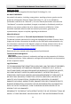
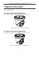
Thermal & Optical Network Turret Camera Quick Start Guide 2 Appearance Description There are two types of thermal network turret cameras. Here are the overviews of Type I camera and Type II camera. 2.1 Type I Turret Camera Appearance Refer to the following figure for type I thermal turret camera overview. Figure 2-1 Type I Thermal Turret Camera Overview 2.2 Type II Turret Camera Appearance Refer to the following figure for type II thermal turret camera overview.
Thermal & Optical Network Turret Camera Quick Start Guide 2.3 Cable Descriptions The cable interfaces of Turret Camera are shown in the figure below. The cables of RS-485, power supply, alarm inputs, alarm outputs, etc. are distinguished by different colors. Please refer to the labels attached on the cables for identification. Audio Output Interface Audio Input Interface Alarm Interface RS-485 Interface Power Interface Network Interface Figure 2-3 Cables of Thermal Turret Camera 2.
Thermal & Optical Network Turret Camera Quick Start Guide 3 Install the Turret Camera Before you start: 1. Check the package contents and make sure that the device in the package is in good condition and all the assembly parts are included. 2. Please turn off the power of the Turret Camera before connecting the cables. Notes: Do not drag the Turret Camera with its waterproof cables, or the waterproof performance is affected. Please remove the protective film on the Turret after the installation.
Thermal & Optical Network Turret Camera Quick Start Guide 3.2 Install Memory Card The micro SD card of two camera models is installed in the same way. Here is an example of SD card installation for type II camera. Steps: 1. Remove the cover on the back of the Turret Camera. Figure 3-1 Remove the Cover 2. Insert the SD card to the SD card slot and install the cover back. Figure 3-2 SD Card Slot 3.3 Install Turret Camera Two types of cameras are installed in the same way.
Thermal & Optical Network Turret Camera Quick Start Guide Figure 3-3 Drill Template 2. Turn the ring anticlockwise and remove it. Note: The ring is only applicable to type II camera. Figure 3-4 Remove the Ring 3. Loosen the screw and dismount the camera body from the base. Figure 3-5 Dismount the Camera from Base 4. Mount the camera base according to the position of drill template.
Thermal & Optical Network Turret Camera Quick Start Guide Drill Template Figure 3-6 Mount the Camera Base 5. Mount the Turret body to the base. Rotate the camera body in the pan direction (0°~360°) or rotate the lens in the tilt direction (0°~80°) to get the desired view angle. 0-360° 0-80° Figure 3-7 Mount the Camera Body 6. Screw the screw to fix the camera body on the camera base. Figure 3-8 Screw the Camera 7. Mount the ring on the camera body, and turn it clockwise to fix the ring.
Thermal & Optical Network Turret Camera Quick Start Guide Figure 3-9 Mount the Ring 3.4 Install Network Cable Water-proof Jacket Purpose: If the camera is installed outdoor, you should use the waterproof accessory or tapes to waterproof the cables. Otherwise the cables might get wet or a short circuit occurs. 3.4.1 Install Network Cable Waterproof Jacket ② ① ③ ④ ⑤ ⑥ Align ③ ④ ⑥ ① Figure 3-10 Install Waterproof Jacket Steps: 1. Feed the network cable through ① and ③ in order. 2.
Thermal & Optical Network Turret Camera Quick Start Guide 6. Secure ① with the ③ in clockwise direction. 3.4.2 Waterproof Other Cables After routing and connecting the cables, use the waterproof tapes to wrap up the cables. Connected cables and spare cables both should be wrapped up as the figures below.
Thermal & Optical Network Turret Camera Quick Start Guide 4 Set the System over the LAN Notes: You shall acknowledge that the use of the product with Internet access might be under network security risks. For avoidance of any network attacks and information leakage, please strengthen your own protection. If the product does not work properly, please contact with your dealer or the nearest service center.
Thermal & Optical Network Turret Camera Quick Start Guide 2. Input the IP address into the address bar of the web browser, and click Enter to enter the activation interface. Note: The default IP address of the system is 192.168.1.64. Figure 4-2 Activation Interface(Web) 3. Create a password and input the password into the password field.
Thermal & Optical Network Turret Camera Quick Start Guide Select inactive device. Input and confirm password. Figure 4-3 SADP Interface 3. Create a password and input the password in the password field, and confirm the password. STRONG PASSWORD RECOMMENDED– We highly recommend you create a strong password of your own choosing (using a minimum of 8 characters, including upper case letters, lower case letters, numbers, and special characters) in order to increase the security of your product.
Thermal & Optical Network Turret Camera Quick Start Guide 3. Change the device IP address to the same subnet with your computer by either modifying the IP address manually or checking the checkbox of Enable DHCP. Figure 4-4 Modify the IP Address 4. Input the password and click Save to activate your IP address modification.
Thermal & Optical Network Turret Camera Quick Start Guide 5 Operate via Web browser 5.1 Access the System System Requirement: Operating System: Microsoft Windows XP SP1 and above version / Vista / Win7 / Server 2003 / Server 2008 32bits CPU: Intel Pentium IV 3.0 GHz or higher RAM: 1G or higher Display: 1024×768 resolution or higher Web Browser: Internet Explorer 7.0 and above version, Apple Safari 5.02 and above version, Mozilla Firefox 5 and above version and Google Chrome8 and above version Steps: 1.
Thermal & Optical Network Turret Camera Quick Start Guide Note: You may have to close the web browser to finish the installation of the plug-in. Figure 5-2 Download Plug-in 6. Reopen the web browser after the installation of the plug-in and repeat the above steps 2-4 to login. Note: For detailed instructions of further configuration, please refer to the user manual of network Turret Camera. 5.
Thermal & Optical Network Turret Camera Quick Start Guide Menu Bar PTZ Control Show or hide PTZ control panel Live View Window Live View Parameters Toolbar Preset/ Patrol/ Pattern Figure 5-3 Live View Page Menu Bar: Click each tab to enter Live View, Playback, Picture, and Configuration page respectively. Click to display the help file of the Turret Camera. Click to logout the system. Live View Window: Display the live video. Toolbar: Operations on the live view page, e.g.
Thermal & Optical Network Turret Camera Quick Start Guide 6 Appendix 6.1 Common Material Emissivity Reference Material Emissivity Human Skin 0.98 PCB 0.91 Cement Concrete 0.95 Ceramics 0.92 Rubber 0.95 Paint 0.93 Wood 0.85 Asphalt 0.96 Brick 0.95 Sand 0.90 Soil 0.92 Cotton 0.98 Cardboard 0.90 White Paper 0.90 Water 0.
Thermal & Optical Network Turret Camera Quick Start Guide 6.2 Frequently Asked Questions (FAQ) 6.2.1 Device Running Error Question: The device fails to start up or reboots repeatedly. The device constantly powers off unexpectedly when you pan/tilt the device or call preset. The device fails to zoom in/out or pan/tilt. Answer: Examine the power supply of the Turret Camera and see whether it meets the requirements. Select the power supply as close as possible.
Thermal & Optical Network Turret Camera Quick Start Guide Examine if the IE plug-in is well installed. Change the Website Blocker settings if necessary. For cross-domain routing, enable the UPnP of device, or set manual mapping to port No. 80, 8000, or 554. Examine if the live view channel amount exceeds the upper limit. Examine the network bandwidth. Question: Focus fails when you test outdoor device in indoor situation. Answer: Restore the device to default settings. Adjust the Min.
UD14811B