
Quick Start Guide


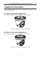


Table Of Contents

Thermal & Optical Network Turret Camera Quick Start Guide
3
2.3 Cable Descriptions
The cable interfaces of Turret Camera are shown in the figure below. The cables of
RS-485, power supply, alarm inputs, alarm outputs, etc. are distinguished by different
colors. Please refer to the labels attached on the cables for identification.
Network Interface
Power Interface
Audio Output Interface
Audio Input Interface
Alarm Interface
RS-485 Interface
Figure 2-3 Cables of Thermal Turret Camera
2.4 Alarm In/Out Connections
This section is only for the Turret Camera with alarm in/out functions.
The Turret Camera can be connected with alarm inputs (0~5VDC) and alarm outputs.
Refer to the following diagrams for alarm output:
JQC-
3FG
Relay
30VDC
GND OUT
L N
~
220V AC
Thermal speed
Dome
Relay Output
(10A 250VAC )
Diagram (left)
Diagram (right)
1A
OUT(n)
OUT(n)
+
-
DC
DC Load
Thermal Speed
Dome
Relay Output
OUT(n)
OUT(n)
Figure 2-4 Alarm Out Connections
The alarm provides the relay output (no voltage), and the external power supply is
required when it connects to the alarm device.
For DC power supply (left diagram), the input voltage must be no more than 30VDC,
1A.
For AC power supply, the external relay must be used (right diagram) to prevent
damages to the Turret Camera and avoid risk of electric shock.