
Quick Start Guide
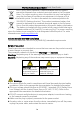
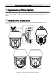
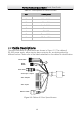
Table Of Contents

Thermal Network Speed dome·Quick Start Guide
4
Table 2-1 Descriptions of Cable Interface
No.
Description
1
Network Cable
2
Video Cable
3
Alarm Out
4
Audio Cable
5
Alarm In
6
RS-485
7
Power Cable
8
SD Card Slot
2.2 Cable Descriptions
The cable interfaces of speed dome are shown in Figure 2-2. The cables of
RS-485, power supply, alarm inputs, alarm outputs, etc. are distinguished by
different colors. Please refer to the labels attached on the cables for identification.
VIDEO
RED AC
24
V
YELLOW
/
GREEN
BLACK AC
24
V
YELLOW R
485
-
ORANGE R
485
+
Power Cable
RS485-
RS485+
Video Cable
Alarm Inputs
Network Cable
Alarm Outputs
Audio Input / Output
Figure 2-2 Cables of Other Speed domes