Thermal Bi-spectrum Network Speed dome User Manual COPYRIGHT © 2018 Hangzhou Hikvision Digital Technology Co.
User Manual of Thermal Bi-spectrum Network Speed dome i User Manual COPYRIGHT © 2018 Hangzhou Hikvision Digital Technology Co., Ltd. ALL RIGHTS RESERVED. Any and all information, including, among others, wordings, pictures, graphs are the properties of Hangzhou Hikvision Digital Technology Co., Ltd. or its subsidiaries (hereinafter referred to be “Hikvision”).
User Manual of Thermal Network Speed dome ii USE CONFORMS THE APPLICABLE LAW. HIKVISION SHALL NOT BE LIABLE IN THE EVENT THAT THIS PRODUCT IS USED WITH ILLEGITIMATE PURPOSES. IN THE EVENT OF ANY CONFLICTS BETWEEN THIS MANUAL AND THE APPLICABLE LAW, THE LATER PREVAILS. Regulatory Information FCC Information Please take attention that changes or modification not expressly approved by the party responsible for compliance could void the user’s authority to operate the equipment.
User Manual of Thermal Network Speed dome iii Safety Instruction These instructions are intended to ensure that the user can use the product correctly to avoid danger or property loss. The precaution measure is divided into ‘Warnings’ and ‘Cautions’: Warnings: Serious injury or death may be caused if any of these warnings are neglected. Cautions: Injury or equipment damage may be caused if any of these cautions are neglected. Warnings Follow these safeguards to prevent serious injury or death.
User Manual of Thermal Network Speed dome iv Table of Contents CHAPTER 1 OVERVIEW ..................................................................................................................... 1 1.1 OVERVIEW........................................................................................................................................1 1.2 SYSTEM REQUIREMENT ...................................................................................................................1 1.
User Manual of Thermal Network Speed dome v 5.2.5 Handling Exception ...................................................................................................................... 52 5.2.6 Detecting Audio Exception ......................................................................................................... 52 5.3 FIRE SOURCE DETECTION CONFIGURATION .................................................................................. 54 5.3.1 Configuring Initial Position ..........
User Manual of Thermal Network Speed dome vi 7.4.5 Configuring DPC Settings ......................................................................................................... 120 7.4.6 Picture in Picture ........................................................................................................................ 121 7.5 CONFIGURING SYSTEM SETTINGS .............................................................................................. 122 7.5.1 System Settings ..............
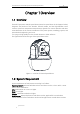
User Manual of Thermal Bi-spectrum Network Speed dome 1 Chapter 1 Overview 1.1 Overview Thermal bi-spectrum network speed dome (named as speed dome in the chapters below) integrates the function of the decoder, thermal camera, and the high-definition zoom camera. It performs temperature measurement, dynamic fire source detection and other smart detections in the remote surveillance of the power system, metallurgy system, and petrochemical engineering, and so on.
User Manual of Thermal Network Speed dome 2 1.3 Functions The main functions of this camera is fire source detection, and temperature measurement, and VCA (video content analysis) functions. Fire Detection Fire Source Detection Shield enables you to shield certain areas from being detected in fire source detection. For fire detection, refer to Section 5.3 Fire Source Detection Configuration.
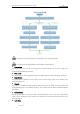
User Manual of Thermal Network Speed dome 3 Start Connect your camera with the alarm device(s). Alarm Device (e.g., siren) Alarm Device /Alarm Sensor? Alarm Sensor (e.g., gas detector) Connect to Alarm Output Terminal (labeled ALARM OUT) Connect to Alarm Input Terminal (labeled ALARM IN) Turn on the Camera. Turn on the Camera. Go to Event>Basic Event>Alarm Output and set the alarm. Go to Event>Basic Event>Alarm Input and set the alarm. Set the schedule for the alarm device.
User Manual of Thermal Network Speed dome 4 In manual tracking mode, when a target object goes directly beneath the speed dome, the video will automatically flips 180 degrees in horizontal direction to maintain continuity of tracking. This function can also be realized by auto mirror image depending on different camera models. Privacy Mask This function allows you to block or mask certain area of a scene, for preventing the personal privacy from recording or live viewing.
User Manual of Thermal Network Speed dome 5 between two presets and the dwell time at the preset are programmable. Pattern A pattern is a memorized series of pan, tilt, zoom, and preset functions. By default the focus and iris are in auto status during the pattern is being memorized. Power Off Memory The speed dome supports the power off memory capability with the predefined resume time. It allows the speed dome to resume its previous position after power is restored.
User Manual of Thermal Bi-spectrum Network Speed dome 6 Chapter 2 Network Connection Before you start: If you want to set the network speed dome via a LAN (Local Area Network), please refer to Section 2.1. If you want to set the network speed dome via a WAN (Wide Area Network), please refer to Section 2.2. 2.
User Manual of Thermal Network Speed dome 7 PC Network Speed Dome Switch Internet NVR Figure 2-2 Connecting via a Switch or a Router 2.1.2 Activating the Speed dome Purpose: You are required to activate the speed dome first before you can use the speed dome. Activation via Web Browser, Activation via SADP, and Activation via client software are supported. In the following sections, activation via web browser and SADP will be taken as examples.
User Manual of Thermal Network Speed dome 8 including at least three of the following categories: upper case letters, lower case letters, numbers, and special characters.) in order to increase the security of your product. And we recommend you reset your password regularly, especially in the high security system, resetting the password monthly or weekly can better protect your product. 4. Confirm the password. 5. Click OK to activate the speed dome and enter the live view interface.
User Manual of Thermal Network Speed dome 9 modifying the IP address manually or checking the checkbox of Enable DHCP. Figure 2-5 Modify the IP Address 6. Input the password and click Save to activate your IP address modification. Activation via Client Software The client software is versatile video management software for multiple kinds of devices. Get the client software from the supplied disk or the official website, and install the software according to the prompts.
User Manual of Thermal Network Speed dome 10 Figure 2-6 Control Panel 2. Click Device Management to enter the Device Management interface, as shown in the figure below. Figure 2-7 Device Management Interface 3. 4. 5. Check the device status from the device list, and select an inactive device. Click Activate to pop up the Activation interface. Create a password and input the password in the password field, and confirm the password.
User Manual of Thermal Network Speed dome 11 STRONG PASSWORD RECOMMENDED–We highly recommend you create a strong password of your own choosing (Using a minimum of 8 characters, including at least three of the following categories: upper case letters, lower case letters, numbers, and special characters.) in order to increase the security of your product.
User Manual of Thermal Network Speed dome 9. 12 Input the password to activate your IP address modification. 2.2 Setting the Network Speed dome over the WAN Purpose: This section explains how to connect the network speed dome to the WAN with a static IP or a dynamic IP. 2.2.1 Static IP Connection Before you start: Please apply a static IP from an ISP (Internet Service Provider). With the static IP address, you can connect the network speed dome via a router or connect it to the WAN directly.
User Manual of Thermal Network Speed dome Network Cable Internet 13 Network Cable Speed Dome PC Figure 2-11 Accessing the Speed dome with Static IP Directly 2.2.2 Dynamic IP Connection Before you start: Please apply a dynamic IP from an ISP. With the dynamic IP address, you can connect the network speed dome to a modem or a router. Connecting the network speed dome via a router Steps: 1. Connect the network speed dome to the router. 2.
User Manual of Thermal Network Speed dome 14 Figure 2-12 Accessing the Speed dome with Dynamic IP The obtained IP address is dynamically assigned via PPPoE, so the IP address always changes after rebooting the speed dome. To solve the inconvenience of the dynamic IP, you need to get a domain name from the DDNS provider (E.g. DynDns.com). Please follow below steps for normal domain name resolution and private domain name resolution to solve the problem.
User Manual of Thermal Network Speed dome 15 Steps: 1. Install and run the IP Server software in a computer with a static IP. 2. Access the network speed dome through the LAN with a web browser or the client software. 3. Enable DDNS and select IP Server as the protocol type. Refer to Section 7.1.1 Configuring DDNS Settings for detailed configuration.
User Manual of Thermal Bi-spectrum Network Speed dome 16 Chapter 3 Access to the Network Speed dome 3.1 Accessing by Web Browsers Steps: 1. Open the web browser. 2. In the address field, input the IP address of the network speed dome, e.g., 192.168.1.64 and press the Enter key to enter the login interface. 3. Activate the speed dome for the first time using, refer to the section 2.1.2 Activating the Speed dome. 4. Select English as the interface language on the top-right of login interface. 5.
User Manual of Thermal Network Speed dome 17 Figure 3-2 Download and Install Plug-in 3.2 Accessing by Client Software The product CD contains the client software. You can view the live video and manage the speed dome with the client software. Follow the installation prompts to install the client software and WinPcap. The configuration interface and live view interface of client software are shown below.
User Manual of Thermal Network Speed dome 18 Figure 3-4 iVMS-4200 Live View Interface If you use third party VMS software, please contact technical support of our branch for camera firmware. For detailed information about client software of our company, please refer to the user manual of the software. This manual mainly introduces accessing to the network speed dome by web browser.
User Manual of Thermal Bi-spectrum Network Speed dome 19 Chapter 4 Basic Operations In this and the following chapters, operation of the speed dome by the web browser will be taken as an example. 4.1 Configuring Local Parameters The local configuration refers to the parameters of the live view and other operations using the web browser. Steps: 1. Enter the Local Configuration interface: Configuration > Local Figure 4-1 Local Configuration Interface 2.
User Manual of Thermal Network Speed dome 20 format. Protocol Type: TCP, UDP, MULTICAST and HTTP are selectable. TCP: Ensures complete delivery of streaming data and better video quality, yet the real-time transmission will be affected. UDP: Provides real-time audio and video streams. MULTICAST: It’s recommended to select the protocol type to MULTICAST when using the Multicast function. HTTP: Allows the same quality as of TCP without setting specific ports for streaming under some network environments.
User Manual of Thermal Network Speed dome 21 4.2 Live View Page Purpose: The live video page allows you to view live video, capture images, realize PTZ control, set/call presets and configure video parameters. Log in the network speed dome to enter the live view page, or you can click on the menu bar of the main page to enter the live view page.
User Manual of Thermal Network Speed dome 22 Pattern function varies depending on the models of speed dome. Live View Parameters: Configure the image size, stream type, plug-in type, and two-way audio of the live video. 4.3 Starting Live View In the live view window as shown in Figure 4-3, click on the toolbar to start the live view of the speed dome. Figure 4-3 Start Live View Table 4-1 Descriptions of the Toolbar Icon Description / / Display in 1× 1/2× 2/3× 3/4× 4 window.
User Manual of Thermal Network Speed dome 23 Double-click on the live video to switch the current live view into full-screen or return to normal mode from the full-screen. Click to select from / to select from / / and display live video in 1 × 1/2 × 2/3 × 3/4 / × 4 window. Click and display live video with the main/ sub stream. The main stream is with a relatively high resolution and needs much bandwidth. The default setting of stream type is Click into and it displays . .
User Manual of Thermal Network Speed dome 24 Click the zoom/iris/focus buttons to realize lens control. Figure 4-4 PTZ Control Panel Table 4-2 Descriptions of PTZ Control Panel Button Name Description Hold and press the direction button to pan/tilt the speed dome. PTZ Control Panel Click and the speed dome keeps panning, the icon turns into . Click the icon again to stop the speed dome. Zoom out/in Click , and the lens zooms out.
User Manual of Thermal Network Speed dome Button Name 25 Description When the image is too dark, click Iris close/open to open the iris. When the image is too bright, click to close the iris. The auxiliary functions include light, wiper, auxiliary focus, lens Auxiliary Functions initialization, manual tracking, 3D positioning, de-icing heater, click-to-thermometry, synchronize FOV Speed Adjustment Preset Patrol Pattern Adjust speed of pan/tilt movements. Refer to 4.4.
User Manual of Thermal Network Speed dome 26 Click to enable/disable the light supplement of the speed dome. This function is reserved. Wiper Click to move the wiper once. Auxiliary Focus The auxiliary focus function is reserved. Click and the lens operates the movements for initialization. Click to enable manual De-Icing function of the device. The de-icing function takes effect when the device inner temperature is ≤ 30°C (86°F).
User Manual of Thermal Network Speed dome 27 zoomed in. 5. Hold down the left mouse button and drag the mouse to the upper left on the live video. The corresponding position will be moved to the center of the live video and zoomed out. 4.4.3 Setting / Calling a Preset Purpose: A preset is a predefined image position. For the defined preset, you can click the calling button to quickly view the desired image position. Setting a Preset: Steps: 1.
User Manual of Thermal Network Speed dome 28 Figure 4-7 Calling a Preset For convenient preset selection, refer to the following steps to navigate to the preset you want. Steps: 1. Select any preset from the list. 2. Click the preset number you need on the keyboard. The following presets are predefined with special commands. You can only call them but not configure them. For instance, preset 99 is the “Start auto scan”. If you call the preset 99, the speed dome starts auto scan function.
User Manual of Thermal Network Speed dome 29 Figure 4-8 Special Preset You may need to use the OSD (On Screen Display) menu when controlling the speed dome remotely. To display the OSD menu on the live view screen, you can call the preset number 95. 4.4.4 Setting / Calling a Patrol Purpose: A patrol is a memorized series of preset function. It can be configured and called on the patrol settings interface. There are up to 8 patrols for customizing. A patrol can be configured with 32 presets.
User Manual of Thermal Network Speed dome 30 Figure 4-9 Adding Presets 4. Configure the preset number, patrol time and patrol speed. Name Description Patrol Time It is the duration staying on one patrol point. The speed dome moves to another patrol point after the patrol time. Patrol Speed It is the speed of moving from one preset to another. 5. Click OK to save a preset into the patrol. 6. Repeat the steps from 3 to 5 to add more presets. 7. Click OK to save all the patrol settings.
User Manual of Thermal Network Speed dome 31 4.4.6 Setting / Calling a Pattern Purpose: A pattern is a memorized series of pan, tilt, zoom, and preset functions. It can be called on the pattern settings interface. There are up to 4 patterns for customizing. Pattern function varies depending on speed dome models. Setting a Pattern: Steps: 1. In the PTZ control panel, click to enter the pattern settings interface. 2. Select a pattern number from the list as shown in Figure 4-12.
User Manual of Thermal Network Speed dome 32 Stop recording the pattern. These 4 patterns can be operated separately and with no priority level. When configuring and calling the pattern, proportional pan is valid; the limit stops and auto flip will be invalid; and the 3D positioning operation is not supported. 4.5 Playback Purpose: This section explains how to view the video files stored in the network disks or memory cards. 4.5.1 Play Back Video Files Steps: 1.
User Manual of Thermal Network Speed dome 33 Figure 4-14 Search Video 3. Click to play the video files found on this date. The toolbar on the bottom of Playback interface can be used to control playing process.
User Manual of Thermal Network Speed dome 34 details. Drag the progress bar with the mouse to locate the exact playback point. You can also input the time and click to locate the playback point in the Set playback time field. You can also click to zoom out/in the progress bar. Figure 4-15 Set Playback Time Figure 4-16 Progress Bar The different colors of the video on the progress bar stand for the different video types as shown in Figure 4-17.
User Manual of Thermal Network Speed dome 2. 35 Set the start time and end time. Click Search. The corresponding video files are listed on the left. Figure 4-18 Video Downloading interface 3. Check the checkbox in front of the video files that you need to download. 4. Click to download the video files. 4.6 Pictures Purpose: This section explains how to view the captured picture files stored in the network disks or the memory cards and download the captured pictures. Steps: 1.
User Manual of Thermal Network Speed dome 36 Figure 4-19 Picture Interface 2. 3. 4. Select the file type of capturing the pictures from the list as timing, alarm, motion, etc. Set the start time and end time. Click Search. The corresponding picture files will be listed. Check the checkbox in front of the files that you need to download. 5. Click © Hikvision to download the files.
User Manual of Thermal Bi-spectrum Network Speed dome 37 Chapter 5 System Configuration 5.1 Storage Settings Before you start: To configure record settings, please make sure that you have the network storage device within the network or the memory card inserted in your speed dome. 5.1.1 Configuring Recording Schedule Purpose: There are two kinds of recording for the speed domes: manual recording and scheduled recording.
User Manual of Thermal Network Speed dome 38 Figure 5-2 Record Parameters Pre-record: The time you set to start recording before the scheduled time or the event. For example, if an alarm triggers recording at 10:00, and the pre-record time is set as 5 seconds, the speed dome starts to record at 9:59:55. The Pre-record time can be configured as No Pre-record, 5 s, 10 s, 15 s, 20 s, 25 s, 30 s or not limited. The pre-record time changes according to the video bitrate.
User Manual of Thermal Network Speed dome 39 Trigger Channel in the Linkage Method of Alarm Input settings interface. For detailed information, please refer to Section Alarm Input. Record Triggered by Motion & Alarm: If you select Motion & Alarm, the video will be recorded when the motion and alarm are triggered at the same time. Besides configuring the recording schedule, you have to configure the settings on the Motion Detection and Alarm Input settings interfaces.
User Manual of Thermal Network Speed dome 40 2. Click 3. Select the timeline of a certain day, click and drag the left button of the mouse to set the capture schedule (the start time and end time of the recording task). 4. After you set the scheduled task, you can click 5. to enter the Capture Schedule interface. and copy the task to other days (optional).
User Manual of Thermal Network Speed dome 41 Steps: 1) Configure the FTP settings and check Upload Picture checkbox in FTP Settings interface. Please refer to Section 7.1.2 Configuring FTP Settings for more details to configure FTP parameters. 2) Check Upload to FTP checkbox in Motion Detection Settings or Alarm Input interface. Refer to Section 5.2.1 Configuring Motion Detection. 3) Check the Enable Event-triggered Snapshot checkbox. 5.1.
User Manual of Thermal Network Speed dome 4. Click 42 to add the network disk. After having saved successfully, you need to reboot the speed dome to activate the settings. Initialize the added network disk. 1. Enter the HDD settings interface (Configuration > Storage > Storage Management > HDD Management), in which you can view the capacity, free space, status, type and property of the disk. Figure 5-6 Storage Management Interface 2.
User Manual of Thermal Network Speed dome 43 Figure 5-8 Quota Settings Up to 8 NAS disks can be connected to the speed dome. To initialize and use the memory card after insert it to the speed dome, please refer to the steps of NAS disk initialization 5.2 Event Configuration Purpose: This section explains how to configure the network speed dome to respond to alarm events, including motion detection, video tampering alarm input, alarm output and exception.
User Manual of Thermal Network Speed dome 44 Figure 5-9 Motion Detection Settings-Normal Steps: (1) Click and drag the mouse on the live video image to draw a motion detection area. (2) Click to finish drawing. You can draw up to 8 motion detection areas on the same image. You can click to clear all of the areas. (3) Move the slider sensitivity of the detection.
User Manual of Thermal Network Speed dome 45 Figure 5-10 Motion Detection Settings-Expert 5. Steps: (1) Set the Schedule Image Settings, there are OFF, Auto-Switch and Scheduled-Switch selectable. If the schedule image switch mode is enabled, you can configure the detection rule for the day and night separately. OFF: Disable the day and night switch. Auto-Switch: Switch the day and night mode according to the illumination automatically. Scheduled-Switch: Switch to the day mode at 6:00 a.m.
User Manual of Thermal Network Speed dome 46 Figure 5-11 Arming Schedule (2) Select the timeline of a certain day, click and drag the mouse to set the arming schedule (the start time and end time of the arming task). (3) After you set the scheduled task, you can click and copy the task to other days (optional). Figure 5-12 Arming Time Schedule (4) After setting the arming schedule, you can click a segment to display the segment arming settings interface to edit the segment record parameters (optional).
User Manual of Thermal Network Speed dome 47 The time of each period cannot be overlapped. Up to 8 periods can be configured for each day. 6. Set the Alarm Actions for Motion Detection. Click tab to enter the Linkage Method interface. You can specify the linkage method when an event occurs. The following contents are about how to configure the different types of linkage method. Figure 5-14 Linkage Method Check the checkbox to select the linkage method.
User Manual of Thermal Network Speed dome 48 You need a FTP server and set FTP parameters first. Refer to Section Configuring FTP Settings for setting FTP parameters. Trigger Alarm Output Trigger one or more external alarm outputs when an event occurs. To trigger an alarm output when an event occurs, please refer to Section 5.2.4 Configuring Alarm Output to set the alarm output parameters. Trigger Recording Record a video when an event occurs.
User Manual of Thermal Network Speed dome 49 Figure 5-15 Tampering Alarm 3. Check Enable checkbox to enable the tampering detection. 4. Click tab to enter the arming schedule setting interface. The arming schedule configuration is the same as the setting of the arming schedule for motion detection. Refer to Section 5.2.1 Configuring Motion Detection. 5. Click tab to select the linkage method taken for tampering, notify surveillance center, send email and trigger alarm output are selectable.
User Manual of Thermal Network Speed dome 50 Figure 5-16 Alarm Input Settings 4. Click tab to enter the arming schedule setting interface. The arming schedule configuration is the same as the setting of the arming schedule for motion detection. Refer to Section 5.2.1 Configuring Motion Detection. 5. Click tab to select the linkage method taken for alarm input, including Notify Surveillance Center, Send Email, Upload to FTP/Memory Card/NAS, Trigger Alarm Output and Trigger Recording.
User Manual of Thermal Network Speed dome 51 5.2.4 Configuring Alarm Output Steps: 1. Enter the Alarm Output settings interface: Configuration> Event > Basic Event > Alarm Output 2. Select one alarm output channel in the Alarm Output dropdown list. 3. Set a name in for the alarm output (optional). 4. The Delay time can be set to 5sec, 10sec, 30sec, 1min, 2min, 5min, 10min or Manual. The delay time refers to the time duration that the alarm output remains in effect after alarm occurs. 5.
User Manual of Thermal Network Speed dome 52 5.2.5 Handling Exception The exception type can be HDD full, HDD error, network disconnected, IP address conflicted and illegal login to the speed domes. Steps: 1. Enter the Exception settings interface: Configuration > Event > Basic Event > Exception 2. Check the checkbox to set the actions taken for the Exception alarm. Refer to Section 5.2.1 Configuring Motion Detection. Figure 5-19 Exception Settings 3. Click to save the settings. 5.2.
User Manual of Thermal Network Speed dome 53 Configuration > Event > Smart Event > Audio Exception Detection Figure 5-20 Audio Exception Detection 2. Check the checkbox of Audio Loss Detection to enable the audio input exception detection. 3. Check the checkbox of Sudden Increase of Sound Intensity Detection checkbox to enable the sudden rise detection. Sensitivity: Range [1-100], the smaller the value the more severe the sound change will trigger the detection.
User Manual of Thermal Network Speed dome 7. Click 54 to save the settings. 5.3 Fire Source Detection Configuration The functions vary depending on the models of speed dome. Start If GPS information is required for platform accessing? YES NO Enable GPS of Position Settings Set the north as the Initial Position Set the VCA resource to Fire Detection Enable Fire Detection (Event > Dynamic Fire Source Detection) Enable Fire Detection Shield.
User Manual of Thermal Network Speed dome 55 5.3.1 Configuring Initial Position Purpose: The initial position is the origin of PTZ coordinates. It can be the factory default initial position. You can also customize the initial position according to your own demand. If you connect the device to the system platform, the platform can mark all the fire positions. Steps: 1. Enter the Position Settings interface: Configuration > PTZ > Position Settings. Figure 5-21 Position Settings 2.
User Manual of Thermal Network Speed dome 56 alarm will be triggered. 4. Enable or disable the alarm uploading and alarm voice warning function. 5. Set GPS settings. (1) Select Longitude-Latitude Mode as Manual. (2) Select longitude and latitude as East or West according to the actual position. (3) Enter the value of longitude and latitude in three textboxes. 6. Click Point to North and save. 7.
User Manual of Thermal Network Speed dome 57 Fire and Smoke Detection as VCA Resource Type. 2. Enter the fire and smoke detection interface: Configuration > Event > Smart Event > Dynamic Fire Source Detection Figure 5-23 Dynamic Fire Source Detection 3. Check the checkbox of Enable Dynamic Fire Source Detection. The function of dynamic fire source detection can only be enabled for camera 2. 4. Select the Application Scene from the list.
User Manual of Thermal Network Speed dome 58 Fire Source Zoom Ratio: Set the zoom ratio of the optical channel when it detects the fire source. In Auto mode, the optical channel changes its zoom ratio until two channels have the same field of view. In Manual mode, you can set the optical zoom ratio. Cancel Repeated Alarm: Enable this function to trigger alarm only once for same place during one day. 6.
User Manual of Thermal Network Speed dome 59 Figure 5-24 Fire Source Detection Shield 2. Click the PTZ control buttons to find the area you want to shield from the smoke detection. 3. Click Draw Area and drag the mouse in the live video window to draw the area. 4. You can drag the corners of the red rectangle area to change its shape and size. 5. Click Stop Drawing to finish drawing or click Clear All to clear all of the areas you set without saving them. 6.
User Manual of Thermal Network Speed dome 60 cannot select Fire and Smoke Detection Mode. 5.4 Temperature Measurement Purpose: When you enable this function, it measures the actual temperature of the spot being monitored. The device alarms when temperature exceeds the temperature threshold value. Before You Start: Enter Configuration > Advanced Configuration > System > VCA Resource Type to select Temperature Measurement + Behavior Analysis as VCA Resource Type. 5.4.
User Manual of Thermal Network Speed dome 61 Enable Color-Temperature: Check the checkbox to display Temperature-Color Ruler in live view. Display Temperature Info. on Stream: Check the checkbox to display temperature information in live view. Add Original Data on Capture: Check the checkbox to add original data on capture. Add Original Data on Stream: Check the checkbox to add original data on stream. Data Refresh Interval: Select the data refresh interval from 1s to 5s.
User Manual of Thermal Network Speed dome 62 Emissivity: Set the emissivity of your target. Note: The emissivity of each object is different. Distance (m): The straight-line distance between the target and the device. Pre-Alarm: When the temperature of target exceeds the Pre-Alarm Threshold, and this status keeps NOT shorter than the Filtering Time, it triggers the Pre-Alarm. Check the checkbox of Pre-Alarm Output to set link the pre-alarm with the connected alarm device.
User Manual of Thermal Network Speed dome 63 panel. Save current scene as certain preset. 4. You can set the preset in live view interface before and call the preset in the temperature measurement and alarm interface. You can set/ call/ clear the preset in temperature measurement interface. Click Synchronize FOV this button to synchronize the FOV of thermal light channel and optical light channel. Configure the parameters.
User Manual of Thermal Network Speed dome 64 c) Set the Alarm Temperature, Pre-Alarm Temperature, and Tolerance Temperature. d) Set the Pre-Alarm Output and Alarm Output with the connected alarm sensor and alarm device. E.g., select Alarm Rule as Above (Average Temperature), and set the Alarm Temperature to 50 ° C, and the device alarms when its average temperature is higher than 50 ° C. For Line Rule: a) Click to show the Alarm Rule setting interface.
User Manual of Thermal Network Speed dome 65 Figure 5-30 Alarm Rule Settings (Area) b) Set the alarm rule. c) Set the Alarm Temperature, Pre-Alarm Temperature, and Tolerance Temperature. d) Set the Pre-Alarm Output and Alarm Output with the connected alarm sensor and alarm device. E.g., select Alarm Rule as Above (Max. Temperature) and set the Alarm Temperature to 40 ° C, and the device alarms when the maximum temperature is higher than 40 ° C. Task 2.
User Manual of Thermal Network Speed dome 66 5.4.3 Linkage Method Purpose: Set the linkage method of the alarm. Steps: 1. Enter Configuration > Temperature Measurement > Linkage Method. 2. Set the arming schedule and linkage method. Arming Schedule: Click on the time bar and drag the mouse to select the time period. Linkage Method: Click Linkage Method and check the checkbox to select the linkage method.
User Manual of Thermal Network Speed dome 67 Chapter 6 VCA Configuration Before you start: Go to Configuration > System > Maintenance > VCA Resource Type and select the VCA Resource as Temperature Measurement + Behavior Analysis. Purpose: You can do intelligent analysis, such as behavior analysis, with the speed dome. Multiple rules can be configured for different requirements. The VCA (Video Content Analysis) function only supported by the thermal channel. 6.1 Configuring VCA Information Steps: 1.
User Manual of Thermal Network Speed dome 68 You can configure the Notify Surveillance Center function which is used for uploading the picture to the surveillance center when and VCA alarm occurs. You can also set the quality and resolution of the picture separately. 5. Click to save the settings. 6.2 Advanced Configuration All the parameters for both behavior analysis and face capture are collected in the advanced configuration page.
User Manual of Thermal Network Speed dome 69 the minimum target size. Displacement Constraint for Target Generation: Range [0-4], the higher the value is, the slower the target is generated, and the higher accuracy the analysis will get. Scene Modes: The scene mode is set to be General by default. Select Distant View when you are far from the targets. Select Indoor when you are indoor. Optical-axis Movement: Check the checkbox when the target moves in the direction of camera's optical -axis.
User Manual of Thermal Network Speed dome 70 Figure 6-3 Zoom Ratio 3. Configure the Scene: Go to VCA > Scene Parameters At most 10 scenes can be added. Different rules and properties can be configured for each scene. Figure 6-4 Scene Parameters Create a Scene: 1) Add New Scene: Click 2) 3) Control the PTZ to get the required scene. Set the scene parameters: Scene Name: Enter a custom scene name. Patrol Sequence: Set the sequence for the scene when doing patrol tracking.
User Manual of Thermal Network Speed dome 71 the tracking duration will not be limited. Limited Tracking: You can check the checkbox to enable/disable the function. If the function is enabled, you can set the limited position for the tracking. 4) Click to save the settings. 1) Rule Configuration: At most 8 rules can be configured for a single scene. Follow the steps below to configure the rule for the scene. Click the Rule tab to enter the rule settings interface.
User Manual of Thermal Network Speed dome 72 Figure 6-6 Arming Schedule 3) Click on the Edit button to edit the arming time segment. Figure 6-7 Schedule Time You can select to copy the settings to whole week or are specific days of the week. At most 8 segments can be configured. 4) Click 1) Configure Arming schedule: Click the Alarm Linkage tab. © Hikvision to save the settings.
User Manual of Thermal Network Speed dome 2) 73 Select a rule from the rule list. Figure 6-8 Alarm Linkage 3) Check the checkbox of corresponding linkage actions to enable it. 4. Advanced Configuration: For details, see section 6.2 Advanced Configuration. Click to save the settings. 6.4 Rule Configuration Demonstration Purpose: This section provides detailed configuration steps for each rule. 6.4.
User Manual of Thermal Network Speed dome 74 Figure 6-9 Select Rule Type 3. (Optional) Configure the size filter, if you want to narrow the detection target to a desired range. a. Check the checkbox of the Filter by, and only filer by pixel is available. b. Click the button and draw a rectangle on the live view image as the Min. size filter. c. 4. Click the button and draw a rectangle on the live view image as the Max. size filter.
User Manual of Thermal Network Speed dome 75 6.4.2 Intrusion Purpose: This function can be used for detecting whether there are people, vehicles and objects intrude into the pre-defined region longer than the set duration. The alarm will be triggered if the rule is broken. Steps: 1. Create new rule: Click on the button 2. 3. 4. Select rule type: Click the dropdown menu and select Intrusion as the rule type. Configure the filtering size: for details, see step 3 in section 6.4.1 Line Crossing.
User Manual of Thermal Network Speed dome 76 6.4.3 Region Entrance Purpose: This function can be used for detecting people, vehicles and objects entering the pre-defined region. The alarm will be triggered if the rule is broken. Steps: 1. Create new rule: Click on the button 2. Select rule type: Click the dropdown menu and select Region Entrance as the rule type. Configure the rule area: 3. Click to add a new rule. on the tool bar of the live view panel. Click the mouse on the live view panel. 4.
User Manual of Thermal Network Speed dome 77 Figure 6-12 Draw Area 4. 5. Configure the filtering size: for details, see step 3 in section 6.4.1 Line Crossing. Enable rules: Check the Enable checkbox of each rule in the rule list to enable the rule. 6. Click © Hikvision to save the settings.
User Manual of Thermal Bi-spectrum Network Speed dome 78 Chapter 7 Speed dome Configuration 7.1 Configuring Network Settings The functions vary depending on the models of speed dome. 7.1.1 Basic Settings Configuring TCP/IP Settings Purpose: TCP/IP settings must be properly configured before you operate the speed dome over network. IPv4 and IPv6 are both supported. Steps: 1.
User Manual of Thermal Network Speed dome 79 Figure 7-1 TCP/IP Settings 2. Configure the NIC settings, including the IPv4(IPv6) Address, IPv4(IPv6) Subnet Mask and IPv4(IPv6) Default Gateway. 3. Click to save the above settings. You can click Test to make sure that the IP address is valid. If the DHCP server is available, you can check to automatically obtain an IP address and other network settings from that server. The valid value range of Maximum Transmission Unit (MTU) is 500 ~ 1500.
User Manual of Thermal Network Speed dome 80 including upper case letters, lower case letters, numbers and special characters) in order to increase the security of your product. Proper configuration of all passwords and other security settings is the responsibility of the installer and/or end-user. Steps: 1. Enter the DDNS settings interface: Configuration > Network > Basic Settings > DDNS Figure 7-3 DDNS Settings 2. Check the Enable DDNS checkbox to enable this feature. 3. Select DDNS Type.
User Manual of Thermal Network Speed dome 81 Steps: (1) Enter the Server Address of the IP Server. (2) Click to save the settings. The Server Address should be entered with the static IP address of the computer that runs the IP Server software. For the IP Server, you have to apply a static IP, subnet mask, gateway and preferred DNS from the ISP. Figure 7-5 IPServer Settings HiDDNS: Steps: (1) Enter the Server Address. (2) Enter the Domain name of the camera.
User Manual of Thermal Network Speed dome 82 Configuring PPPoE Settings Purpose: If you have no router but only a modem, you can use Point-to-Point Protocol over Ethernet (PPPoE) function. Steps: 1. Enter the PPPoE settings interface: Configuration > Network > Basic Settings > PPPoE Figure 7-7 PPPoE Settings 2. Check the Enable PPPoE checkbox to enable this feature. 3. Enter User Name, Password, and Confirm password for PPPoE access. The User Name and Password should be assigned by your ISP.
User Manual of Thermal Network Speed dome 83 Configuration > Network > Basic Settings > Port Figure 7-8 Port Settings 2. Set the HTTP port, RTSP port and port of the speed dome. HTTP Port: The default port number is 80. RTSP Port: The default port number is 554. HTTPS Port: The default port number is 443. Server Port: The default port number is 8000. 3. Click to save the settings.
User Manual of Thermal Network Speed dome 84 Figure 7-9 Port Mapping Mode 4. Click to save the settings. 7.1.2 Advanced Settings Configuring SNMP Settings Purpose: You can use SNMP to get speed dome status and parameters related information. Before you start: Before setting the SNMP, please use the SNMP software and manage to receive the speed dome information via SNMP port. By setting the Trap Address, the speed dome can send the alarm event and exception messages to the surveillance center.
User Manual of Thermal Network Speed dome 85 Figure 7-10 SNMP Settings 2. Check the corresponding version checkbox (Enable SNMP v1, Enable SNMP v2c, Enable SNMP v3) to enable the feature. 3. Configure the SNMP settings. The configuration of the SNMP software should be the same as the settings you configure here. 4. Click to save and finish the settings. Configuring FTP Settings Purpose: You can set a FTP server and configure the following parameters for uploading captured pictures. Steps: 1.
User Manual of Thermal Network Speed dome 86 Configuration > Network > Advanced Settings > FTP Figure 7-11 FTP Settings 2. Configure the FTP settings, including server address, port, user name, password, directory, and upload type. The server address supports both the domain name and IP address formats. For your privacy and to better protect your system against security risks, we strongly recommend the use of strong passwords for all functions and network devices.
User Manual of Thermal Network Speed dome 87 files will be saved in a sub-folder in FTP server. The name of folder can be defined as shown in following Figure 7-13. Figure 7-13 Child Directory Upload type: To enable uploading the captured picture to the FTP server. 3. Click to save the settings. 4. You can click Test to confirm the configuration.
User Manual of Thermal Network Speed dome 88 SMTP Server: The SMTP Server IP address or host name (e.g., smtp.263xmail.com). SMTP Port: The SMTP port. The default TCP/IP port for SMTP is 25. E-mail encryption: None, SSL, and TLS are selectable. When you select SSL or TLS and disable STARTTLS, e-mails will be sent after encrypted by SSL or TLS. The SMTP port should be set as 465 for this encryption method.
User Manual of Thermal Network Speed dome 89 Figure 7-15 Platform Access Settings 2. Check the checkbox of Enable to enable the platform access function of the device. 3. Select the Platform Access Mode from the dropdown list. 4. Set the Server IP. 5. Click to save the settings Configuring HTTPS Settings Purpose: HTTPS is consisted by SSL&HTTP. It is used for encryption transmission, identity authentication network protocol which enhances the security of WEB accessing.
User Manual of Thermal Network Speed dome 90 Figure 7-17 Create Self-signed Certificate 3) Enter the country, host name/IP, validity and other information. 4) Click OK to save the settings. OPTION 2: Start the installation when signed certificate is available. 1) Select Signed certificate is available, Start the installation directly. 2) Click Browse to upload the available certificate. 3) Click Install button to install the certificate. 4) Click OK to save the settings.
User Manual of Thermal Network Speed dome 91 When the port number is not the default number 443, the format of the URL is https://IP address:port number, eg., https://192.168.1.64:81. Configuring QoS Settings Purpose: QoS (Quality of Service) can help solve the network delay and network congestion by configuring the priority of data sending. Steps: 1. Enter the QoS settings interface: Configuration >Advanced Configuration > Network > QoS Figure 7-19 QoS Settings 2.
User Manual of Thermal Network Speed dome 92 Authenticator Network Switch Speed Dome Internet Authentication Server PC PC RADIUS Server Figure 7-20 Protected LAN Before connecting the Network Camera to the protected LAN, please apply a digital certificate from a Certificate Authority. The network camera requests access to the protected LAN via the authenticator (a switch). The switch forwards the identity and password to the authentication server (RADIUS server).
User Manual of Thermal Network Speed dome 93 Figure 7-21 802.1X Settings 3. 4. Check the Enable IEEE 802.1X checkbox to enable it. Configure the 802.1X settings, including user name and password. The EAP-MD5 version must be identical with that of the router or the switch. 5. Click to finish the settings. The camera reboots when you save the settings. 6. After the configuration, connect the camera to the protected network.
User Manual of Thermal Network Speed dome 94 7.2 Configuring Video and Audio Settings 7.2.1 Configuring Video Settings Steps: 1. Enter the Video settings interface: Configuration > Video/Audio > Video Figure 7-22 Configure Video Settings 2. Select the Channel No. in the dropdown list you want to configure. 3. Select the Stream Type of the speed dome to main stream (normal), sub-stream or third stream.
User Manual of Thermal Network Speed dome 95 Select the bitrate type to constant or variable. Video Quality: When bitrate type is selected as Variable, 6 levels of video quality are selectable. Frame Rate: The frame rate is to describe the frequency at which the video stream is updated and it is measured by frames per second (fps). A higher frame rate is advantageous when there is movement in the video stream, as it maintains image quality throughout. Max. Bitrate: Set the max. bitrate to 256~16384Kbps.
User Manual of Thermal Network Speed dome 96 frames from the original video when the network bandwidth is insufficient. Smoothing: It refers to the smoothness of the stream. The higher value of the smoothing, the better fluency of the stream, though, the video quality may not be so satisfied. The lower value of the smoothing, the higher quality of the stream, though it may appear not fluent. 5. Click to save the settings. 7.2.2 Configuring Audio Settings Steps: 1.
User Manual of Thermal Network Speed dome 97 7.2.3 Configuring ROI Settings Purpose: ROI (Region of Interest) encoding is used to enhance the quality of images which are specified in advance. There are two different ROI methods: Fixed Region and Dynamic Region. When Fixed Region is enabled, image quality of ROI area will be enhanced and image quality of other areas will be reduced. When Dynamic Region is enabled, image quality of tracking target will be enhanced.
User Manual of Thermal Network Speed dome 98 Figure 7-25 Region of Interest (2) ROI for Fixed Region Steps: 1. Check Enable checkbox to enable the Fixed Region function. 2. Select a stream type. You can set the ROI function for main stream, sub stream or third stream. 3. Click and then click-and-drag the mouse to draw a red frame in the live view image. You can click to clear it. The number of areas supported in ROI function varies depending on the models of speed dome. 4. Select the Region No.
User Manual of Thermal Network Speed dome 99 7.3 PTZ Configuration On the event configuration page, click to show the PTZ control panel or click hide it. Click the direction buttons to control the pan/tilt movements. Click the zoom/iris/focus buttons to realize lens control. The functions vary depending on the models of speed dome. to 7.3.1 Configuring Basic PTZ Parameters Purpose: You can configure the basic PTZ parameters, including proportional pan, preset freezing, preset speed, etc. 1.
User Manual of Thermal Network Speed dome 100 Figure 7-26 Basic PTZ Configuration Interface 2. Configure the following settings: Basic Parameters: Enable/disable proportional pan and preset freezing, set the preset speed, keyboard control speed, and auto scan speed. Proportional Pan: If you enable this function, the pan/tilt speeds change according to the amount of zoom.
User Manual of Thermal Network Speed dome 101 (left/right, up/down). Steps: 1. Enter the Limit configuration interface: Configuration > PTZ > Limit Figure 7-27 Configure the PTZ Limit 2. Click the checkbox of Enable Limit and choose the limit type as manual stops or scan stops. Manual Stops: When manual limit stops are set, you can operate the PTZ control panel manually only in the limited surveillance area.
User Manual of Thermal Network Speed dome 102 and etc.) automatically after a period of inactivity (park time). Scheduled Tasks function is prior to Park Action function. When these two functions are set at the same time, only the Scheduled Tasks function takes effect. Pattern function varies depending on speed dome models. Steps: 1. Enter the Park Action settings interface: Configuration > PTZ > Park Action Figure 7-28 Set the Park Action 2. Check the checkbox of Enable Park Action. 3.
User Manual of Thermal Network Speed dome 103 Figure 7-29 Draw the Privacy Mask 2. Click the PTZ control buttons to find the area you want to set the privacy mask. 3. Click 4. You can drag the corners of the red rectangle area to draw a polygon mask. 5. Click ; click and drag the mouse in the live video window to draw the area. to finish drawing or click to clear all of the areas you set without saving them. 6.
User Manual of Thermal Network Speed dome 104 7.3.5 Configuring Scheduled Tasks Purpose: You can configure the network speed dome to perform a certain action automatically in a user-defined time period. Steps: 1. Enter the Scheduled Task settings interface: Configuration> PTZ > Scheduled Tasks Figure 7-31 Configure Scheduled Tasks 2. Check the checkbox of Enable Scheduled Task. 3. Set the Park Time. You can set the park time (a period of inactivity) before the speed dome starts the scheduled tasks. 4.
User Manual of Thermal Network Speed dome 6. After you set the scheduled task, you can click 105 and copy the task to other days (optional). Figure 7-33 Edit the Schedule and Task Type The time of each task cannot be overlapped. Up to 10 tasks can be configured for each day. 7. Click to save the settings. 7.3.6 Clearing PTZ Configurations Purpose: You can clear PTZ configurations in this interface, including all presets, patrols, privacy masks, PTZ limits, scheduled tasks and park actions.
User Manual of Thermal Network Speed dome 1. Enter the Prioritize PTZ interface: Configuration > PTZ > Prioritize PTZ. Figure 7-34 Position Settings 2. Select Network or RS-485 from the dropdown list 3. Set the delay time (Range 2-200s). 4. Click to save the settings. 7.3.8 Position and Vandal-Resistance Alarm Settings Steps: 1. Enter the Position Settings interface: Configuration > PTZ > Position Settings. The actual interface may vary from model to model.
User Manual of Thermal Network Speed dome 107 Figure 7-35 Position Settings 2. Set the vandal-resistance alarm. (1) Slide the bar to adjust the sensitivity of vandal-resistance detection. (2) Check the checkbox of Upload Vandal-Resistance Alarm to upload the vandal-resistance alarm. (3) Check the checkbox of Enable Vandal-Resistance Alarm Voice Warning to enable the voice warning of vandal-resistance alarm. 3. Set GPS settings. (4) Select Longitude-Latitude Mode as Manual.
User Manual of Thermal Network Speed dome 108 5. Optionally, you can click Enable Saved Ratio to set the camera to the saved zoom ratio. 6. Click Set Scan Area and set the left/right/up/down limits with the PTZ control panel and Iris+/- button. 7. Optionally, you can click Clear to delete the saved scan area. 8. Click Save to save the settings and the Linear Scan Area shows Scan area saved. 9. Click Start Linear Scan and Stop Linear Scan to start and stop the saved linear scan.
User Manual of Thermal Network Speed dome 109 7.4 Configuring Image Settings On the event configuration page, click to show the PTZ control panel or click hide it. Click the direction buttons to control the pan/tilt movements. Click the zoom/iris/focus buttons to realize lens control. The functions vary depending on the models of speed dome. to 7.4.
User Manual of Thermal Network Speed dome 110 3. You can select the Scene in the dropdown list with different predefined image parameters. 4. Set the image parameters of the speed dome. Setting the Channel Camera 1 Image Adjustment Brightness This feature is used to adjust brightness of the image. The value ranges from 0 to 100. Contrast This feature enhances the difference in color and light between parts of an image. The value ranges from 0 to 100.
User Manual of Thermal Network Speed dome 111 Shutter Priority: The value of shutter needs to be adjusted manually. The iris and gain values will be adjusted automatically according to the brightness of the environment. Figure 7-39 Manual Shutter Manual: In Manual mode, you can adjust the values of Gain, Shutter, Iris manually. Limit Gain This feature is used to adjust gain of the image. The value ranges from 0 to 100. Slow Shutter This function can be used in underexposure condition.
User Manual of Thermal Network Speed dome 112 The minimum focus value varies depending on the models of speed dome. Day/Night Switch Day/Night Switch The Day/Night Switch mode can be set to Auto, Day, Night and Scheduled-Switch. This function varies depending on the models of speed dome. Auto: In Auto mode, the day mode and night mode can switch automatically according to the light condition of environment. Figure 7-41 Auto Mode Sensitivity Day: In Day mode, the speed dome displays color image.
User Manual of Thermal Network Speed dome 113 under back light circumstances. When there are both very bright and very dark areas simultaneously in the field of view, WDR balances the brightness level of the whole image and provide clear images with details. You can enable or disable the WDR function as shown in Figure 7-43. The wide dynamic level ranges from 0 to 100. Figure 7-43 WDR This function varies depending on the models of speed dome.
User Manual of Thermal Network Speed dome 114 In Auto-Tracking mode, white balance is continuously being adjusted in real-time according to the color temperature of the scene illumination. This function varies depending on the models of speed dome. Image Enhancement This function varies depending on the models of speed dome. 3D Digital Noise Reduction You can set Digital Noise Reduction function to Normal and adjust the Noise Reduction Level as shown in Figure 7-45. The level ranges from 0 to 100.
User Manual of Thermal Network Speed dome 115 Figure 7-48 Optical Image Stabilization Figure 7-49 Electronic Image Stabilization Video Adjustment Mirror If you turn the MIRROR function on, the image will be flipped. It is like the image in the mirror. The flip direction can be set to OFF or CENTER. This function varies depending on the models of speed dome. Video Standard You can set the Video Standard to 50hz(PAL) or 60hz(NTSC) according to the video system in your country.
User Manual of Thermal Network Speed dome 116 Setting the Channel Camera 2 Figure 7-50 Camera No. 2 Image Settings Image Adjustment Brightness This feature is used to adjust brightness of the image. The value ranges from 0 to 100. Contrast This feature enhances the difference in color and light between parts of an image. The value ranges from 0 to 100.
User Manual of Thermal Network Speed dome 117 OFF: DNR is disabled. Normal Mode: Set the DNR level from 0~ 100, and the default value is 50. Expert Mode: Set the DNR level from both space DNR level [0~100] and time DNR level [0~100] in Expert Mode. Palettes The palettes allow you to select the desired colors. white hot, black hot, fusion 1, rainbow, fusion 2, ironbow 1, ironbow2, sepia, color 1, color 2, ice fire, rain, red hot, and green hot are selectable.
User Manual of Thermal Network Speed dome 118 7.4.2 Configuring OSD Settings Purpose: The speed dome supports following on screen displays: Time: Supports for time display. Camera Name: Identifies the name of speed dome. You can customize the on screen display of time. Steps: 1. Enter the OSD settings interface: Configuration > Image > OSD Settings 2. Select the channel No.. Figure 7-51 OSD Settings 3. Check the corresponding checkbox to select the display of speed dome name, date or week if required. 4.
User Manual of Thermal Network Speed dome 119 Figure 7-52 Adjust OSD Location 7. Click to activate above settings. 7.4.3 Configuring Text Overlay Settings Purpose: You can customize the text overlay. Steps: 1. Enter the Text Overlay settings interface: Configuration > Image > OSD Settings 2. Check the checkbox in front of textbox to enable the on-screen display. 3. Input the characters in the textbox. 4.
User Manual of Thermal Network Speed dome 120 Figure 7-53 VCA Rule Display 1. Set the font size of the VCA rules. 2. Customize the color of line and frame for Normal, Pre-Alarm, and Alarm. 3. Click to save the settings. 7.4.5 Configuring DPC Settings DPC (Defective Pixel Correction) refers to the function that the camera can correct the defective pixels on the LCD which are not performing as expected.
User Manual of Thermal Network Speed dome 121 Steps: 1. Select Auto from the modes. 2. Click to start correction. Manual DPC Correction Steps: 1. Select Manual from the modes. 2. Point to the defective pixel, and click 3. 4. Click to start correction. (Optional) Click to cancel the correction. to adjust the position. This function varies depending on the models of speed dome. 7.4.
User Manual of Thermal Network Speed dome 122 Figure 7-55 Picture in Picture 3. Drag the red frame to adjust the picture in picture site. 4. Click Save to activate above settings. 7.5 Configuring System Settings 7.5.1 System Settings Viewing Basic Information Enter the Device Information interface: Configuration > System > System Settings > Basic Information In the Basic Information interface, you can edit the Device Name and Device No..
User Manual of Thermal Network Speed dome 123 Figure 7-56 Device Information Time Settings Purpose: You can follow the instructions in this section to configure the time which can be displayed on the video. There are Time Zone, Time Synchronization, Daylight Saving Time (DST) functions for setting the time. Time Synchronization consists of auto mode by Network Time Protocol (NTP) server and manual mode.
User Manual of Thermal Network Speed dome 124 Steps: (1) Check the radio button to enable the NTP function. (2) Configure the following settings: Server Address: IP address of NTP server. NTP Port: Port of NTP server. Interval: The time interval between the two synchronizing actions by NTP server. It can be set from 1 to 10080 minutes. Figure 7-58 Time Sync by NTP Server You can click to make sure that the NTP server is connected.
User Manual of Thermal Network Speed dome 125 Select the Time Zone Purpose: When the speed dome is taken to another time zone, you can use the Time Zone function to adjust the time. The time will be adjusted according to the original time and the time difference between the two time zones. From the Time Zone dropdown menu as shown in Figure 7-60, select the Time Zone in which the speed dome locates.
User Manual of Thermal Network Speed dome 126 Figure 7-62 RS-485 Settings 2. Set the RS-485 parameters and click to save the settings. The Baud rate, PTZ Protocol and PTZ Address parameters of the speed dome should be exactly the same as those of the control device. 7.5.2 Maintenance Upgrade & Maintenance Rebooting the Positioning system Steps: 1. Enter the Maintenance interface: 2. Configuration > System > Maintenance > Upgrade & Maintenance: 3.
User Manual of Thermal Network Speed dome 127 Figure 7-63 Restore Default Settings Information Export Steps: 1. Enter the Maintenance interface: Configuration > System > Maintenance > Upgrade & Maintenance: 2. Click Device Parameters and input the encryption password twice to encrypt the config file. Figure 7-64 Encryption Configuration File 3. Select the path to export the current configuration file. You can configure the other cameras with the file. 4.
User Manual of Thermal Network Speed dome 128 Figure 7-66 File Decryption Upgrading the System Steps: 1. Enter the Maintenance interface: Configuration >System > Maintenance > Upgrade & Maintenance 2. Select Firmware or Firmware Directory. Firmware: when you select Firmware, you need to find the firmware in your computer to upgrade the device. Firmware Directory: You need to find the directory where the firmware locates. The device can find the firmware in the directory automatically. 3.
User Manual of Thermal Network Speed dome 129 1. Enter the Log interface: Configuration >System > Maintenance > Log Figure 7-68 Log Searching Interface 2. Set the log search conditions to specify the search, including the Major Type, Minor Type, Start Time and End Time as shown in Figure 7-68. 3. Click to search log files. The matched log files will be displayed on the Log interface. 4. To export the log files, click Save Log to save the log files in your computer. System Service Steps: 1.
User Manual of Thermal Network Speed dome 130 Figure 7-69 Hardware Settings 5. Click button to activate the settings. VCA Resource Type Purpose: Before using the VCA function of the camera, you should select the VCA resource type first. To use Temperature Measurement and Behavior Analysis, select Temperature Measurement and Behavior Analysis. To use Temperature Measurement and Behavior Analysis and Fire Detection function, select Temperature Measurement and Behavior Analysis and Fire Detection.
User Manual of Thermal Network Speed dome 131 Once you select any of the resources, the other VCA rules cannot be enabled. 7.5.3 Security Configuring Authentication Security Purpose: You can specifically secure the stream data of live view. Steps: 1. Enter the Authentication interface: Configuration> System> Security > Authentication 2. Set the authentication mode for each authentication type.
User Manual of Thermal Network Speed dome 132 Figure 7-71 IP Address Filter 2. Check the checkbox of Enable IP Address Filter. 3. Select the type of IP Address Filter in the dropdown list, Forbidden and Allowed are selectable. 4. Set the IP Address Filter list. Add an IP Address Steps: (1) Click Add to add an IP. (2) Input the IP Adreess. Figure 7-72 Add an IP (3) Click OK to finish adding. Modify an IP Address Steps: (1) Left-click an IP address from filter list and click Modify.
User Manual of Thermal Network Speed dome 133 Figure 7-73 Modify an IP (3) Click OK to finish modifying. Delete an IP Address Left-click an IP address from filter list and click Delete. Delete all IP Addresses Click Clear to delete all the IP addresses. 5. Click to save the settings. Configure Security Service Settings Steps: 1. Enter the Security Service interface: Configuration> System > Security > Security Service 2. Check the checkbox to enable the SSH function.
User Manual of Thermal Network Speed dome 134 Figure 7-74 User Information Add a User Steps: 1. Click 2. Input the new User Name, select Level and input Password. to add a user. For your privacy and to better protect your system against security risks, we strongly recommend the use of strong passwords for all functions and network devices.
User Manual of Thermal Network Speed dome 135 Figure 7-75 Add a User Modify a User Steps: 1. Left-click to select the user from the list and click . 2. Modify the User Name, Level or Password. 3. In the Basic Permission field and Camera Configuration field, you can check or uncheck the permissions. 4. Click to finish the user modification.
User Manual of Thermal Network Speed dome 136 Figure 7-76 Modify a User Delete a User Steps: 1. Left-click the user name you want to delete and click 2. Click on the pop-up dialogue box to delete the user. Online Users Enter the Online Users configuration interface: Configuration > System > User Management > Online Users © Hikvision .
User Manual of Thermal Network Speed dome 137 Figure 7-77 Online Users You can see the current users who are visiting the device through this interface. User information, such as user name, level, IP address, and operation time, is displayed in the User List. Click Refresh to refresh the list.
User Manual of Thermal Bi-spectrum Network Speed dome 138 Appendix SADP Software Introduction Description of SADP SADP (Search Active Devices Protocol) is a kind of user-friendly and installation-free online device search tool. It searches the active online devices within your subnet and displays the information of the devices. You can also modify the basic network information of the devices using this software.
User Manual of Thermal Network Speed dome can click 139 to expand the device table and hide the network parameter panel on the right side, or click to show the network parameter panel. Modify network parameters Steps: 1. Select the device to be modified in the device list and the network parameters of the device will be displayed in the Modify Network Parameters panel on the right side. 2. Edit the modifiable network parameters, e.g. IP address and port number. 3.
UD10891B