
User Manual
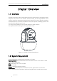
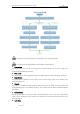
Table Of Contents
- Chapter 1 Overview
- Chapter 2 Network Connection
- Chapter 3 Access to the Network Speed dome
- Chapter 4 Basic Operations
- Chapter 5 System Configuration
- Chapter 6 VCA Configuration
- Chapter 7 Speed dome Configuration
- 7.1 Configuring Network Settings
- 7.2 Configuring Video and Audio Settings
- 7.3 PTZ Configuration
- 7.4 Configuring Image Settings
- 7.5 Configuring System Settings
- Appendix

User Manual of Thermal Network Speed dome
© Hikvision
3
Alarm Device /Alarm
Sensor?
Start
Alarm Device
(e.g., siren)
Alarm Sensor (e.g.,
gas detector)
Connect to Alarm Output
Terminal (labeled ALARM OUT)
END
Connect your camera with the alarm device(s).
Connect to Alarm Input
Terminal (labeled ALARM IN)
Turn on the Camera. Turn on the Camera.
Go to Event>Basic Event>Alarm Output
and set the alarm.
Go to Event>Basic Event>Alarm Input
and set the alarm.
Set the schedule for the alarm device. Set the schedule for the sensor.
Link the alarm to e-mail,
center, alarm out , etc.
Set Alarm Linkage for events.
The functions vary depending on the models of positioning system.
The functions vary depending on the models of speed dome.
Bi-spectrum
The speed dome has two lens, an optical one and a thermal one, and two images are
respectively provided by each lens.
PTZ Limits
The speed dome can be programmed to move within the PTZ limits (left/right, up/down).
Scan Modes
The speed dome provides 5 scan modes: auto scan, tilt scan, frame scan, random scan
and panorama scan.
Presets
A preset is a predefined image position. When the preset is called, the speed dome will
automatically move to the defined position. The presets can be added, modified, deleted
and called.
Label Display
The on-screen label of the preset title, azimuth/elevation, zoom, time and speed dome
name can be displayed on the monitor. The displays of time and speed dome name can
be programmed.
Auto Flips