Thermal & Optical Bi-spectrum Network Stable PTZ Camera Quick Start Guide
Thermometric Network Positioning System·Quick Start Guide © 2021 Hangzhou Hikvision Digital Technology Co., Ltd. All rights reserved. About this Manual The Manual includes instructions for using and managing the Product. Pictures, charts, images and all other information hereinafter are for description and explanation only. The information contained in the Manual is subject to change, without notice, due to firmware updates or other reasons.
Thermometric Network Positioning System·Quick Start Guide YOU ACKNOWLEDGE THAT THE NATURE OF INTERNET PROVIDES FOR INHERENT SECURITY RISKS, AND HIKVISION SHALL NOT TAKE ANY RESPONSIBILITIES FOR ABNORMAL OPERATION, PRIVACY LEAKAGE OR OTHER DAMAGES RESULTING FROM CYBER-ATTACK, HACKER ATTACK, VIRUS INFECTION, OR OTHER INTERNET SECURITY RISKS; HOWEVER, HIKVISION WILL PROVIDE TIMELY TECHNICAL SUPPORT IF REQUIRED.
Thermometric Network Positioning System·Quick Start Guide Regulatory Information FCC Information FCC compliance: This equipment has been tested and found to comply with the limits for a Class A digital device, pursuant to part 15 of the FCC Rules. These limits are designed to provide reasonable protection against harmful interference when the equipment is operated in a commercial environment.
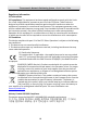
Thermometric Network Positioning System·Quick Start Guide Symbol Conventions The symbols that may be found in this document are defined as follows. Symbol Description Danger Indicates a hazardous situation which, if not avoided, will or could result in death or serious injury. Caution Indicates a potentially hazardous situation which, if not avoided, could result in equipment damage, data loss, performance degradation, or unexpected results.
Thermometric Network Positioning System·Quick Start Guide ● or generates direct current. Ensure correct wiring of the terminals for connection to an AC mains supply. Battery ● ● ● ● ● ● ● ● Risk of explosion if the battery is replaced by an incorrect type. Dispose of used batteries according to the instructions. Il y a risque d'explosion si la batterie est remplacée par une batterie de type incorrect. Mettre au rebut les batteries usagées conformément aux instructions.
Thermometric Network Positioning System·Quick Start Guide Maintenance ● ● ● ● ● ● ● If the product does not work properly, please contact your dealer or the nearest service center. We shall not assume any responsibility for problems caused by unauthorized repair or maintenance. A few device components (e.g., electrolytic capacitor) require regular replacement. The average lifespan varies, so periodic checking is recommended. Contact your dealer for details.
Thermometric Network Positioning System·Quick Start Guide Table of Contents 1 Preparation .................................................................................................. 1 1.1 Basic Requirement ................................................................................................... 1 1.2 Checking Installing Environment ............................................................................. 1 1.3 Preparing Cables ...........................................................
Thermometric Network Positioning System·Quick Start Guide 1 Preparation 1.1 Basic Requirement All the electronic operation should be strictly compliance with the electrical safety regulations, fire prevention regulations and other related regulations in your local region. Check the package contents and make sure that the device in the package is in good condition and all the assembly parts are included. Use the system according to the working environment requirement. 1.
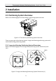
Thermometric Network Positioning System·Quick Start Guide 2 Installation 2.1 Positioning System Overview Refer to the following figure for thermometry positioning system overview. Figure 2-1 Thermometry Positioning System Overview There are two types of positioning systems: Large-sized Housing positioning system and small-sized housing positioning system. 2.1.1 Large-sized Housing Positioning System Dimensions Refer to the following figure for the large-sized positioning system dimensions (unit: mm).
Thermometric Network Positioning System·Quick Start Guide 650 10 666.1 202 239 259 4 529 -Φ 222 259 Figure 2-3 Large-sized Housing Positioning System Dimensions (2) 2.1.2 Small-sized Housing Positioning System Dimensions Refer to the following figure for the small-sized positioning system dimensions. 808.7 239 202 4Φ 10 R517.
Thermometric Network Positioning System·Quick Start Guide 2.1.3 Positioning System Components Description Refer to the following figures for the components dimensions of the positioning system.
Thermometric Network Positioning System·Quick Start Guide 2.2 Cable Descriptions The cable interfaces of positioning system are shown in Figure 2-8. The cables of RS-485, power supply, alarm inputs, alarm outputs, etc. are distinguished by different colors. Please refer to the labels attached on the cables for identification.
Thermometric Network Positioning System·Quick Start Guide 2.3 Installing the Positioning System 2.3.1 Monitoring Distance Range Electric lens is adopted for the thermometric channel of positioning system. It supports auto-focus function and remote focus function. For different lens focal length, the monitoring range is shown in the table below: Table 2-1 Monitoring Range (Pixel Interval: 17um) Lens Focal Length/mm 75 100 150 MRAD 0.23 0.17 0.
Thermometric Network Positioning System·Quick Start Guide 2.3.2 Wiring Please fully take into consideration the installation environment and position of the positioning system when you plan for the wiring. In order to make sure the stable power supply and signal transmission, please closely follow the rules below: Please get familiar with the installation environment before you wiring, including the wiring distance, wiring environment, keeping magnetic-field interference away, etc.
Thermometric Network Positioning System·Quick Start Guide 6.Secure ① with the ③ in clockwise direction. Waterproof Other Cables After routing and connecting the cables, use the waterproof tapes to wrap up the cables. Connected cables and spare cables both should be wrapped up as the figures below. Figure 2-9 Waterproof Cable 2.3.3 Installing Positioning System Steps: 1. Open the package and take out the housing, positioning system base and other accessories such as screws.
Thermometric Network Positioning System·Quick Start Guide 3. Align the red lines respectively on the aviation connectors of the positioning system base to the red lines on the connectors under the housing. Push the aviation connectors into the corresponding interfaces. Connect the Aviation Plug Figure 2-11 Connect the Aviation Plug 160.6 202 238.6 4. Rotate and tighten the aviation connectors. 5. Drill four holes on the installation position according to the Figure 2-12. 6.
Thermometric Network Positioning System·Quick Start Guide 1). Lead the screw (Model: M8×45) through the spring washer and flat washer. 2). Align the screw holes of the base with the installation holes and fix the positioning system with the screws. Note: Make sure the bubble of the spirit level is right in the middle so that the positioning system is placed horizontally. Spring Washer Flat Washer Figure 2-13 Dimension Figure of the Positioning System Base 3).
Thermometric Network Positioning System·Quick Start Guide Installing Holes Wall Sealing Interface Figure 2-14 Fix the Junction Box 4). Fix the junction box with expansion screws. 5). Loosen four screws of the junction box cover with the wrench (supplied), and open the junction box cover, as shown in the figure below. Figure 2-15 Open the Junction Box 6). Move the cover according to the direction of the arrow to take apart the cover. Figure 2-16 Take Apart the Junction Box Cover 7).
Thermometric Network Positioning System·Quick Start Guide - Route the power cord of external power source through sealing opening No.1, and attach the cable with live wire and null wire from the power adapter respectively. - Connect the live wire to the L terminal of power surge protector, and connect the null wire to the N terminal of power surge protector. - Route the network cable from switch or client-end through sealing opening No.
Thermometric Network Positioning System·Quick Start Guide Network Interface External Power Supply Connect PTZ Camera Sealing Ring Power Output (48 VDC) Network Cable · Connect Yellow Cables to GND Power Adapter Power Surge Protector Power Input · Connect Brown Cables to Terminal L · Connect Blue cables to Terminal N Figure 2-17 Cable Connection of Junction Box 8). Cover the junction box and tighten the screws. Note: For detailed information of sealing the interfaces, refer to the section 2.3.4.
Thermometric Network Positioning System·Quick Start Guide 2.3.4 Sealing the Junction Box Steps: 1. Take apart the cover of the junction box, and rotate the screw nut to take out the sealing ring inside. 2. Lead the cables through the sealing ring, and the screw nut, as shown in Figure 2-18. 3. Use a proper wrench (not supplied) to tighten the screw nuts. Sealing Ring Screw Nut Cables Figure 2-18 Seal the Cables 4. Tighten the screws to fix the cover.
Thermometric Network Positioning System·Quick Start Guide 2.3.5 Finishing Installing Power on the positioning system and the device will perform self-test action. If the positioning system starts normally and plays the live view, it is successfully installed. If the positioning system cannot start normally, check the cable connection.
Thermometric Network Positioning System·Quick Start Guide 3 Setting the System over the LAN You shall acknowledge that the use of the product with Internet access might be under network security risks. For avoidance of any network attacks and information leakage, please strengthen your own protection. If the product does not work properly, please contact with your dealer or the nearest service center.
Thermometric Network Positioning System·Quick Start Guide 2. Power on the system, and connect the system to the network. 3. Input the IP address into the address bar of the web browser, and click Enter to enter the activation interface. The default IP address of the system is 192.168.1.64. Figure 3-2 Activation Interface(Web) 4. Create a password and input the password into the password field.
Thermometric Network Positioning System·Quick Start Guide Select inactive device. Input and confirm password. Figure 3-3 SADP Interface 3. Create a password and input the password in the password field, and confirm the password. STRONG PASSWORD RECOMMENDED– We highly recommend you create a strong password of your own choosing (using a minimum of 8 characters, including upper case letters, lower case letters, numbers, and special characters) in order to increase the security of your product.
Thermometric Network Positioning System·Quick Start Guide 3. Change the device IP address to the same subnet with your computer by either modifying the IP address manually or checking the checkbox of Enable DHCP. Figure 3-4 Modify the IP Address 4. Input the password and click Save to activate your IP address modification.
Thermometric Network Positioning System·Quick Start Guide 4 Accessing via Web browser System Requirement: Operating System: Microsoft Windows XP SP1 and above version / Vista / Win7 / Server 2003 / Server 2008 32bits CPU: Intel Pentium IV 3.0 GHz or higher RAM: 1G or higher Display: 1024×768 resolution or higher Web Browser: Internet Explorer 7.0 and above version, Apple Safari 5.02 and above version, Mozilla Firefox 5 and above version and Google Chrome8 and above version Steps: 1. Open the web browser.
Thermometric Network Positioning System·Quick Start Guide You may have to close the web browser to finish the installation of the plug-in. Figure 4-2 Download Plug-in Figure 4-3 Install Plug-in 6. Reopen the web browser after the installation of the plug-in and repeat the above steps 2-4 to login. For detailed instructions of further configuration, please refer to the user manual of network positioning system.
Thermometric Network Positioning System·Quick Start Guide 5 Appendix 5.1 Common Material Emissivity Reference Material Emissivity Human Skin 0.98 PCB 0.91 Cement Concrete 0.95 Ceramics 0.92 Rubber 0.95 Paint 0.93 Wood 0.85 Asphalt 0.96 Brick 0.95 Sand 0.90 Soil 0.92 Cotton 0.98 Cardboard 0.90 White Paper 0.90 Water 0.
Thermometric Network Positioning System·Quick Start Guide 5.2 Frequently Asked Questions (FAQ) 5.2.1 Device Running Error Question: The device fails to start up or reboots repeatedly. The device constantly powers off unexpectedly when you pan/tilt the device or call preset. The device fails to zoom in/out or pan/tilt. Answer: Examine the power supply of the device and see whether it meets the requirements. Use the nearby power supply or connect the ancillary equipment (e.g. UPS).
Thermometric Network Positioning System·Quick Start Guide Examine if the IE plug-in is well installed. Change the Website Blocker settings if necessary. For cross-domain routing, enable the UPnP of device, or set manual mapping to port No. 80, 8000, or 554. Examine if the live view channel amount exceeds the upper limit. Examine the network bandwidth. Question: Focus fails when you test outdoor device in indoor situation. Answer: Restore the device to default settings. Adjust the Min.
UD22520B