
Quick Start Guide
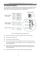


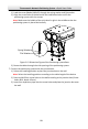

Table Of Contents

Thermometric Network Positioning System
·Quick Start Guide
5
2.2 Cable Descriptions
The cable interfaces of positioning system are shown in Figure 2-8. The cables of RS-485,
power supply, alarm inputs, alarm outputs, etc. are distinguished by different colors.
Please refer to the labels attached on the cables for identification.
Alarm Cable:
7-ch Input
Power Cable
AUDIO_IN
AUDIO_OUT
AUDIO_GND
ALARM_OUT1
ALARM_IN1
ALARM_IN2
ALARM_IN3
ALARM_IN4
ALARM_IN5
ALARM_IN6
ALARM_IN7
ALARM_GND
Alarm Input
Video Cable
Control Line
Power Cable
DC48V+
GND
ALARM_COM1
ALARM_OUT2
ALARM_COM2
Alarm Cable:
2-ch Output
Audio Cable:
DC48V-
Alarm Output
Audio Cable
Network Cable
Figure 2-8 Cables of Other Positioning Systems
The power cable has three terminals: 48 VDC+, 48 VDC-, and Grounding.
The video cable is CVBS cable.
The control line is the RS-485 cable.
The alarm cables include alarm input cables and alarm output cables. Connect
terminal ALARM-IN with terminal GND, and connect terminal ALARM-OUT and
terminal ALARM-COM.
The audio cable has audio input and audio output cables. Connect terminal
AUDIO_IN and terminal AUDIO_GND, and connect terminal AUDIO_OUT and
terminal AUDIO_GND.
Connect the network cable to network interface to get network signal.