
Quick Start Guide
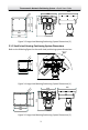
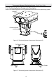

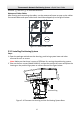

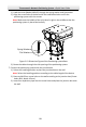

Table Of Contents

Thermometric Network Positioning System
·Quick Start Guide
9
3. Align the red lines respectively on the aviation connectors of the positioning system
base to the red lines on the connectors under the housing. Push the aviation
connectors into the corresponding interfaces.
Connect the
Aviation Plug
Figure 2-11 Connect the Aviation Plug
4. Rotate and tighten the aviation connectors.
5. Drill four holes on the installation position according to the Figure 2-12.
6. Fix the positioning system with the screws (Model: M8x45) on the installation
position.
Unit: mm
222
259.1
160.6
202
238.6
4
-
Φ
10
Figure 2-12 Positioning System Base Dimensions
Notes:
Only standard screws (Model: M8x45) for the positioning system are allowed in
this step. The thickness of the steel plate is more than 5mm.
If no thread is on the base of bracket, you need to tighten the screw nuts (Model:
M8).