Thermal Bi-spectrum Network PTZ Device User Manual
User Manual of Thermal Bi-spectrum Network PTZ Device User Manual © 2019 Hangzhou Hikvision Digital Technology Co., Ltd. All rights reserved. This Manual is the property of Hangzhou Hikvision Digital Technology Co., Ltd. or its affiliates (hereinafter referred to as “Hikvision”), and it cannot be reproduced, changed, translated, or distributed, partially or wholly, by any means, without the prior written permission of Hikvision.
User Manual of Thermal Bi-spectrum Network PTZ Device Symbol Convention The symbols that may be found in this document are defined as follows. Symbol Description Provides additional information to emphasize or supplement important points of the main text. Indicates a potentially hazardous situation, which if not avoided, could result in equipment damage, data loss, performance degradation, or unexpected results.
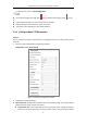
User Manual of Thermal Bi-spectrum Network PTZ Device Table of Contents Chapter 1 Overview ........................................................................................................................ 1 1.1 Overview .................................................................................................................................. 1 1.2 System Requirement ................................................................................................................ 1 1.
User Manual of Thermal Bi-spectrum Network PTZ Device 5.2.6 Configure Burning-Prevention ........................................................................................... 56 5.2.7 Detect Audio Exception ...................................................................................................... 57 5.3 Fire Source Detection Configuration ...................................................................................... 58 5.3.1 Configure Initial Position ......................
User Manual of Thermal Bi-spectrum Network PTZ Device 7.3.5 Configure Picture Overlay ................................................................................................ 123 7.3.6 Configure DPC Settings .................................................................................................... 124 7.3.7 Picture in Picture .............................................................................................................. 124 7.4 Configure System Settings .............
User Manual of Thermal Bi-spectrum Network PTZ Device Chapter 1 Overview 1.1 Overview Thermal bi-spectrum network device (named as device in the chapters below) integrates the function of the decoder, thermal camera, and the high-definition zoom camera. It performs temperature measurement, dynamic fire source detection and other smart detections in the remote surveillance of the power system, metallurgy system, and petrochemical engineering, and so on.
User Manual of Thermal Bi-spectrum Network PTZ Device For VCA function, refer to 5.5PTZ Configuration it. On the event configuration page, click to show the PTZ control panel or click to hide Click the direction buttons to control the pan/tilt movements. Click the zoom/iris/focus buttons to realize lens control. The functions vary depending on the models of device. 1.3.
User Manual of Thermal Bi-spectrum Network PTZ Device slower for keeping the image from moving too fast on the live view image. Preset Freezing: This function enables the live view to switch directly from one scene defined by a preset to another, without showing the middle areas between these two, to ensure the surveillance efficiency. It can also reduce the use of bandwidth in a digital network system. Preset freezing function is invalid when you calling a pattern.
User Manual of Thermal Bi-spectrum Network PTZ Device Figure 1-2 Configure the PTZ Limit 2. Click Enable Limit and choose the limit type as manual stops or scan stops. Manual Stops: When manual limit stops are set, you can operate the PTZ control panel manually only in the limited surveillance area. Scan Stops: When scan limit stops are set, the random scan, frame scan, auto scan, tilt scan, panorama scan is performed only in the limited surveillance area.
User Manual of Thermal Bi-spectrum Network PTZ Device 1. Go to the. Park Action settings interface: Configuration > PTZ > Park Action Figure 1-3 Set the Park Action 2. Check Enable Park Action. 3. Set the Park Time as the inactivity time of the device before it starts the park actions. 4. Choose Action Type the from the dropdown list. Figure 1-4 Action Types 5. Select the Action Type ID from the dropdown list. 6. Click . 1.3.
User Manual of Thermal Bi-spectrum Network PTZ Device Figure 1-5 Draw the Privacy Mask 2. Click the PTZ control buttons to find the area you want to set the privacy mask. 3. Click 4. You can drag the corners of the red rectangle area to draw a polygon mask. 5. Click ; click and drag the mouse in the live video window to draw the area. to finish drawing or click to clear all of the areas you set without saving them. 6.
User Manual of Thermal Bi-spectrum Network PTZ Device 1.3.5 Configure Scheduled Tasks Purpose: You can configure the network device to perform a certain action automatically in a user-defined time period. Steps: 1. Go to the. Scheduled Task settings interface: Configuration> PTZ > Scheduled Tasks Figure 1-7 Configure Scheduled Tasks 2. Check Enable Scheduled Task. 3. Set the Park Time. You can set the park time (a period of inactivity) before the device starts the scheduled tasks. 4.
User Manual of Thermal Bi-spectrum Network PTZ Device Figure 1-9 Edit the Schedule and Task Type The time of each task cannot be overlapped. Up to 10 tasks can be configured for each day. 7. Click . 1.3.6 Clear PTZ Configurations Purpose: You can clear PTZ configurations in this interface, including all presets, patrols, privacy masks, PTZ limits, scheduled tasks and park actions. Pattern function varies depending on device models. Steps: 1. Go to the.
User Manual of Thermal Bi-spectrum Network PTZ Device Figure 1-10 Position Settings 2. Select Network or RS-485 from the dropdown list 3. Set the delay time (Range 2-200s). 4. Click . 1.3.8 Position and Vandal-Resistance Alarm Settings Steps: 1. Go to the. Position Settings interface: Configuration > PTZ > Position Settings. The actual interface may vary from model to model. Figure 1-11 Position Settings 2. Set the vandal-resistance alarm.
User Manual of Thermal Bi-spectrum Network PTZ Device 3. Set GPS settings. (1) Select Longitude-Latitude Mode as Manual. (2) Select longitude and latitude as East or West according to the actual position. (3) Input the value of longitude and latitude in three textboxes. 4. Click . 1.3.9 Configure Linear Scan Steps: 1. Go to the linear scan interface: Configuration > Advanced Configuration> PTZ > Linear Scan. Figure 1-12 Linear Scan 2. 3. 4. 5. 6. Select Camera 1 or Camera 2 from the Channel No. list.
User Manual of Thermal Bi-spectrum Network PTZ Device VCA Configuration. Alarm Input and Output Refer to the figure below to configure the alarm devices and sensors. Start Connect your camera with the alarm device(s). Alarm Device (e.g., siren) Alarm Device /Alarm Sensor? Alarm Sensor (e.g., gas detector) Connect to Alarm Output Terminal (labeled ALARM OUT) Connect to Alarm Input Terminal (labeled ALARM IN) Turn on the Camera. Turn on the Camera.
User Manual of Thermal Bi-spectrum Network PTZ Device automatically flips 180 degrees in horizontal direction to maintain continuity of tracking. This function can also be realized by auto mirror image depending on different camera models. Privacy Mask This function allows you to block or mask certain area of a scene, for preventing the personal privacy from recording or live viewing.
User Manual of Thermal Bi-spectrum Network PTZ Device iris are in auto status during the pattern is being memorized. Power Off Memory The device supports the power off memory capability with the predefined resume time. It allows the device to resume its previous position after power is restored. Scheduled Task A time task is a preconfigured action that can be performed automatically at a specific date and time.
User Manual of Thermal Bi-spectrum Network PTZ Device Chapter 2 Network Connection Before you start: If you want to set the network device via a LAN (Local Area Network), please refer to Section 2.1. If you want to set the network device via a WAN (Wide Area Network), please refer to Section 2.2. 2.
User Manual of Thermal Bi-spectrum Network PTZ Device PC Network Speed Dome Internet Switch NVR Figure 2-2 Connect via a Switch or a Router 2.1.2 Activate the Device Purpose: You are required to activate the device first before you can use the device. Activation via Web Browser, Activation via SADP, and Activation via client software are supported. In the following sections, activation via web browser and SADP will be taken as examples.
User Manual of Thermal Bi-spectrum Network PTZ Device We highly recommend you create a strong password of your own choosing (using a minimum of 8 characters, including upper case letters, lower case letters, numbers, and special characters) in order to increase the security of your product. And we recommend you reset your password regularly, especially in the high security system, resetting the password monthly or weekly can better protect your product. 5. Click OK.
User Manual of Thermal Bi-spectrum Network PTZ Device Figure 2-5 Modify the IP Address 6. Input the password and click Save. 2.2 Set the Network Device over the WAN Purpose: This section explains how to connect the network device to the WAN with a static IP or a dynamic IP. 2.2.1 Static IP Connection Before you start: Please apply a static IP from an ISP (Internet Service Provider). With the static IP address, you can connect the network device via a router or connect it to the WAN directly.
User Manual of Thermal Bi-spectrum Network PTZ Device Network Cable Network Cable Speed Dome Internet Network Cable Router with Static IP PC Figure 2-6 Access the Device through Router with Static IP Connect the network device with static IP directly You can also save the static IP in the device and directly connect it to the internet without using a router. Refer to Section 2.1.2 for detailed IP address configuration of the device.
User Manual of Thermal Bi-spectrum Network PTZ Device 4. Set port mapping. E.g. 80, 8000 and 554 ports. The steps for port mapping vary depending on different routers. Please call the router manufacturer for assistance with port mapping. 5. Apply a domain name from a domain name provider. 6. Configure the DDNS settings. 7. Visit the device via the applied domain name. Connecting the network device via a modem Purpose: This device supports the PPPoE auto dial-up function.
User Manual of Thermal Bi-spectrum Network PTZ Device Figure 2-10 Private Domain Name Resolution Steps: 1. Install and run the IP Server software in a computer with a static IP. 2. Access the network device through the LAN with a web browser or the client software. 3. Enable DDNS and select IP Server as the protocol type. Refer to Section 7.1.1 Configure DDNS for detailed configuration.
User Manual of Thermal Bi-spectrum Network PTZ Device Chapter 3 Access to the Network Device You can access to the device by using web browser or client software. Here is the introduction of accessing by web browser. Steps: 1. Open the web browser. 2. In the address field, input the IP address of the network device, e.g., 192.168.1.64 and press the Enter key to go to the. login interface. 3. Activate the device for the first time using, refer to the section 2.1.2 Activate the Device. 4.
User Manual of Thermal Bi-spectrum Network PTZ Device Figure 3-2 Download and Install Plug-in 22
User Manual of Thermal Bi-spectrum Network PTZ Device Chapter 4 Basic Operations In this and the following chapters, operation of the device by the web browser will be taken as an example. 4.1 Configure Local Parameters The local configuration refers to the parameters of the live view and other operations using the web browser. Steps: 1. Go to the. Local Configuration interface: Configuration > Local Figure 4-1 Local Configuration Interface 2.
User Manual of Thermal Bi-spectrum Network PTZ Device under some network environments. Play Performance: Set the play performance to Shortest Delay, or Auto. Rules: You can enable or disable the rules of dynamic analysis for motion here. Fire Point: Locate Highest Temperature Point, and Frame Fire Point are selectable. Display the highest temperature area as point or frame. Display Temperature Info.: Display temperature information or not with temperature measurement rule configured.
User Manual of Thermal Bi-spectrum Network PTZ Device Descriptions of the live view page: Menu Bar PTZ Control & Quick Setup Camera Number Live View Window Preset/Patrol Settings Toolbar Figure 4-2 Live View Page Menu Bar: Click each tab to enter Live View, Playback, Picture, and Configuration page respectively. Click to display the help file of the device. Click to logout the system. Live View Window: Display the live video. Toolbar: Operations on the live view page, e.g.
User Manual of Thermal Bi-spectrum Network PTZ Device Figure 4-3 Start Live View 4.3.1 Toolbar Description Table 4-1 Descriptions of the Toolbar Icon Description Start/Stop Live view. / / Icon / / Description Manually capture the pictures. Display in 1×1/2×2/3×3/4×4 Live view with the main/sub window. / stream. / Manual start/stop recording. / Start/Stop Two-way Audio. / View previous / next page.
User Manual of Thermal Bi-spectrum Network PTZ Device Click and it displays . Click to enable two-way audio and the icon turns into . Click the icon again to stop two-way audio. Click to start live view and the icon turns into Click to capture the picture. Click to start recording and the icon turns into . Click the icon again to stop live view. . Click the icon again to stop recording.
User Manual of Thermal Bi-spectrum Network PTZ Device Figure 4-4 PTZ Control Panel Table 4-2 Descriptions of PTZ Control Panel Button Name Description Hold and press the direction button to pan/tilt the device. PTZ Control Panel Click and the device keeps panning, the icon turns into . Click the icon again to stop the device. Zoom out/in Click , and the lens zooms out. Click Focus near/far , the lens zooms in, click , the lens focus far and the items far away gets clear.
User Manual of Thermal Bi-spectrum Network PTZ Device Button Name Description When the image is too dark, click Iris close/open to open the iris. When the image is too bright, click to close the iris. The auxiliary functions include light, wiper, auxiliary focus, lens Auxiliary Functions initialization, manual tracking, 3D positioning, de-icing heater, click-to-thermometry, synchronize FOV Speed Adjustment Refer to 4.4.3 for detailed Preset information of setting preset. Refer to 4.4.
User Manual of Thermal Bi-spectrum Network PTZ Device Click to enable/disable the light supplement of the device. This function is reserved. Wiper Click to move the wiper once. Auxiliary Focus The auxiliary focus function is reserved. Click and the lens operates the movements for initialization. Click to enable manual De-Icing function of the device. The de-icing function takes effect when the device inner temperature is ≤ 30°C (86°F).
User Manual of Thermal Bi-spectrum Network PTZ Device 4.4.3 Set / Call a Preset Purpose: A preset is a predefined image position. For the defined preset, you can click the calling button to quickly view the desired image position. Set a Preset: Steps: 1. In the PTZ control panel, select a preset number from the preset list. Figure 4-6 Set a Preset 2. Use the PTZ control buttons to move the lens to the desired position. • Pan the speed dome to the right or left. • Tilt the speed dome up or down.
User Manual of Thermal Bi-spectrum Network PTZ Device 2. Click the preset number you need on the keyboard. The following presets are predefined with special commands. You can only call them but not configure them. For instance, preset 99 is the “Start auto scan”. If you call the preset 99, the speed dome starts auto scan function. Pattern function varies depending on the models of speed dome.
User Manual of Thermal Bi-spectrum Network PTZ Device 4.4.4 Set / Call a Patrol Purpose: A patrol is a memorized series of preset function. It can be configured and called on the patrol settings interface. There are up to 8 patrols for customizing. A patrol can be configured with 32 presets. Before you start: Please make sure that the presets you want to add into a patrol have been defined. Set a Patrol: Steps: 1. In the PTZ control panel, click to go to the. patrol settings interface. 2.
User Manual of Thermal Bi-spectrum Network PTZ Device Figure 4-10 Call a Preset 4.4.5 Set / Call a Pattern Purpose: A pattern is a memorized series of pan, tilt, zoom, and preset functions. It can be called on the pattern settings interface. There are up to 4 patterns for customizing. Pattern function varies depending on device models. Set a Pattern: Steps: 1. In the PTZ control panel, click to go to the. pattern settings interface. 2. Select a pattern number from the list as shown in Figure 4-11.
User Manual of Thermal Bi-spectrum Network PTZ Device 5. Click to save all the pattern settings. Buttons on the Patterns interface: Buttons Description Start the selected patrol/pattern. Stop current patrol/pattern. Set the selected preset/patrol. Delete the selected preset/patrol/pattern. Start recording a pattern. Stop recording the pattern. These 4 patterns can be operated separately and with no priority level.
User Manual of Thermal Bi-spectrum Network PTZ Device 4.6 Playback Purpose: This section explains how to view the video files stored in the network disks or memory cards. 4.6.1 Play Back Video Files Steps: 1. Click on the menu bar to enter playback interface. Figure 4-12 Playback Interface 2. Select the date and click . Figure 4-13 Search Video 3. Click to play the video files found on this date. The toolbar on the bottom of Playback interface can be used to control playing process.
User Manual of Thermal Bi-spectrum Network PTZ Device Table 4-5 Description of the buttons Button Operation Button Operation Play Capture a picture Start/Stop clipping Pause / video files Audio on and adjust Stop / volume/Mute Speed down Download Speed up Playback by frame Display in / / / 1×1/2×2/3×3/4×4 Show full screen window. Play recorded videos Stop all Playback of different cameras asynchronously. Play recorded videos of different cameras synchronously.
User Manual of Thermal Bi-spectrum Network PTZ Device Synchronously play recorded videos of different channels Steps: 1. Click to enable synchronous playback function. 2. Choose camera channels. 3. Setting date and time of recorded videos. 4. Click to view the videos of optical channel and thermal channel synchronously. Asynchronously play recorded videos of different channels Steps: 1. Click 2. 3. 4. 5. 6. to enable asynchronous playback function. Choose Channel No: 1.
User Manual of Thermal Bi-spectrum Network PTZ Device Figure 4-18 Video Downloading interface 3. Select the video files that you need to download. 4. Click . 4.7 Picture Purpose: This section explains how to view the captured picture files stored in the network disks or the memory cards and download the captured pictures. Steps: 1. Click .
User Manual of Thermal Bi-spectrum Network PTZ Device Figure 4-19 Picture Interface 2. 3. 4. Select the channel No. and file type of capturing the pictures from the list as timing, alarm, motion, etc. Set the start time and end time. Click Search. The corresponding picture files will be listed. Select the files that you need to download. 5. Click .
User Manual of Thermal Bi-spectrum Network PTZ Device Chapter 5 System Configuration 5.1 Storage Settings Before you start: To configure record settings, please make sure that you have the network storage device within the network or the memory card inserted in your device. 5.1.1 Configure Recording Schedule Purpose: There are two kinds of recording for the devices: manual recording and scheduled recording. In this section, you can follow the instructions to configure the scheduled recording.
User Manual of Thermal Bi-spectrum Network PTZ Device Figure 5-2 Record Parameters Pre-record: The time you set to start recording before the scheduled time or the event. For example, if an alarm triggers recording at 10:00, and the pre-record time is set as 5 seconds, the device starts to record at 9:59:55. The pre-record time changes according to the video bitrate. Post-record: The time you set to stop recording after the scheduled time or the event.
User Manual of Thermal Bi-spectrum Network PTZ Device recorded when the external alarm is triggered or the motion is detected. Besides configure the recording schedule, you have to configure the settings on the Motion Detection and Alarm Input settings interfaces. Record Triggered by VCA events: If you select VCA, the video will be recorded when the either of the VCA events is triggered. Besides configure the recording schedule, you have to configure the settings on the VCA interface.
User Manual of Thermal Bi-spectrum Network PTZ Device segment capture settings interface to edit the segment capture parameters. (optional) Figure 5-4 Segment Snapshot Settings 6. Click 7. Click . You can select the stream type of the capture. . 8. Check Enable Timing Snapshot to enable continuous snapshot, and configure the schedule of timing snapshot. Check Enable Event-triggered Snapshot to enable event-triggered snapshot. 9. Select the format, resolution, quality of the snapshot. 10.
User Manual of Thermal Bi-spectrum Network PTZ Device Steps: Add the network disk 1. Go to the. NAS (Network-Attached Storage) settings interface: Configuration > Storage > Storage Management > Net HDD Figure 5-5 Select Net HDD Type 2. Input the IP address and the file path of the network disk. 3. Select the mounting type. NFS and SMB/CIFS are selectable. You can set the user name and password to guarantee the security if SMB/CIFS is selected.
User Manual of Thermal Bi-spectrum Network PTZ Device Figure 5-6 Storage Management Interface 2. If the status of the disk is Uninitialized, check the corresponding checkbox to select the disk and click Format to start initializing the disk. 3. When the initialization completed, the status of disk will become Normal as shown in Figure 5-7. Figure 5-7 View Disk Status Define the Quota for Record and Pictures 1. Input the quota percentage for picture and for record. 2.
User Manual of Thermal Bi-spectrum Network PTZ Device This section explains how to configure the network device to respond to alarm events, including motion detection, video tampering alarm input, alarm output and exception. These events can trigger the alarm actions, such as Send Email, Notify Surveillance Center, etc. For example, when motion detection is triggered, the network device sends a notification to an e-mail address.
User Manual of Thermal Bi-spectrum Network PTZ Device Figure 5-9 Motion Detection Settings-Normal Steps: (1) Click and drag the mouse on the live video image to draw a motion detection area. (2) Click to finish drawing. You can draw up to 8 motion detection areas on the same image. You can click Clear All to clear all of the areas. (3) Move the slider to set the sensitivity of the detection.
User Manual of Thermal Bi-spectrum Network PTZ Device Figure 5-10 Motion Detection Settings-Expert Steps: 5. (1) Set the Schedule Image Settings, there are OFF, Auto-Switch and Scheduled-Switch selectable. If the schedule image switch mode is enabled, you can configure the detection rule for the day and night separately. OFF: Disable the day and night switch. Auto-Switch: Switch the day and night mode according to the illumination automatically. Scheduled-Switch: Switch to the day mode at 6:00 a.m.
User Manual of Thermal Bi-spectrum Network PTZ Device Figure 5-11 Arming Schedule (2) Select the timeline of a certain day, click and drag the mouse to set the arming schedule (the start time and end time of the arming task). (3) After you set the scheduled task, you can click (optional).
User Manual of Thermal Bi-spectrum Network PTZ Device The time of each period cannot be overlapped. Up to 8 periods can be configured for each day. 6. Set the Alarm Actions for Motion Detection. Click tab to go to the. Linkage Method interface. You can specify the linkage method when an event occurs. The following contents are about how to configure the different types of linkage method. Figure 5-14 Linkage Method Check to select the linkage method.
User Manual of Thermal Bi-spectrum Network PTZ Device To trigger an alarm output when an event occurs, please refer to Section 5.2.4 Configure Alarm Output to set the alarm output parameters. Trigger Recording Record a video when an event occurs. You have to set the recording schedule to realize this function. Please refer to Section 5.1.1 Configure Recording Schedule for settings the recording schedule. 5.2.
User Manual of Thermal Bi-spectrum Network PTZ Device 5. Click tab to select the linkage method taken for tampering, notify surveillance center, send email and trigger alarm output are selectable. Refer to Section 5.2.1 Configure Motion Detection. 6. Click . 5.2.3 Configure Alarm Input Steps: 1. Go to the. Alarm Input settings interface: Configuration > Event > Basic Event > Alarm Input 2. Choose the alarm input No. and the Alarm Type. The alarm type can be NO (Normally Open) and NC (Normally Closed).
User Manual of Thermal Bi-spectrum Network PTZ Device 8. Click . Figure 5-17 Linkage Method 5.2.4 Configure Alarm Output Steps: 1. Go to the. Alarm Output settings interface: Configuration> Event > Basic Event > Alarm Output 2. Select one alarm output channel in the Alarm Output dropdown list. 3. Set a name in for the alarm output (optional). 4. The Delay time can be set to 5sec, 10sec, 30sec, 1min, 2min, 5min, 10min or Manual.
User Manual of Thermal Bi-spectrum Network PTZ Device Figure 5-18 Alarm Output Settings 7. You can copy the settings to other alarm outputs. 8. Click . 5.2.5 Handle Exception The exception type can be HDD full, HDD error, network disconnected, IP address conflicted and illegal login to the devices. Steps: 1. Go to the. Exception settings interface: Configuration > Event > Basic Event > Exception 2. Check to set the actions taken for the Exception alarm. Refer to Section 5.2.
User Manual of Thermal Bi-spectrum Network PTZ Device Figure 5-19 Exception Settings 3. Click . 5.2.6 Configure Burning-Prevention Purpose: This function enable the movement of lens to protect it from high temperature damage. Steps: 1. Go to Burning-Prevention interface. 2. Check Enable. 3. Set the protection mode as Lens Movement. 4. Set the protection duration. 5. Click Save.
User Manual of Thermal Bi-spectrum Network PTZ Device Figure 5-20 Burning-Prevention 5.2.7 Detect Audio Exception Purpose: When you enable this function and audio exception occurs, the alarm actions will be triggered. Steps: 1. Go to the video audio exception detection interface: Configuration > Event > Smart Event > Audio Exception Detection Figure 5-21 Audio Exception Detection 2. Check Audio Loss Detection to enable the audio input exception detection. 3.
User Manual of Thermal Bi-spectrum Network PTZ Device trigger the detection. Sound Intensity Threshold: Range [1-100], it can filter the sound in the environment, the louder the environment sound, the higher the value should be. You can adjust it according to the actual environment. 4. Check Sudden Decrease of Sound Intensity Detection to enable the sudden drop detection. Sensitivity: Range [1-100], the smaller the value the more severe the sound change will trigger the detection. 5.
User Manual of Thermal Bi-spectrum Network PTZ Device Start If GPS information is required for platform accessing? YES NO Enable GPS of Position Settings Set the north as the Initial Position Set the VCA resource to Fire Detection Enable Fire Detection (Event > Dynamic Fire Source Detection) Enable Fire Detection Shield. If the PTZ function is supported by the camera? YES Set the application scene and zoom parameters. NO Enable the patrol/park/linear scan.
User Manual of Thermal Bi-spectrum Network PTZ Device 1. Go to the. Position Settings interface: Configuration > PTZ > Position Settings. Figure 5-22 Position Settings 2. Set the compass parameters. (1) Select PT Mode as Manual. (2) Click the PTZ control buttons to find the north direction; you can also call a defined preset and set it as the north direction. (3) Click Set as North to save the position.
User Manual of Thermal Bi-spectrum Network PTZ Device Figure 5-23 PTZ Configuration 8. Click the PTZ control buttons to find a position as the initial position of the device; you can also call a defined preset and set it as the initial position of the device. 9. Click Set to save the position. Call/delete an Initial Position: You can click to call the initial position. You can click to delete the initial position and restore the factory default initial position. 5.3.
User Manual of Thermal Bi-spectrum Network PTZ Device Figure 5-24 Dynamic Fire Source Detection 3. Check Enable Dynamic Fire Source Detection. The function of dynamic fire source detection can only be enabled for camera 2. 4. Check Display Fire Source Info on Stream to add fire source information on stream, and the overlay will be displayed in live view. 5. Select the Application Scene from the list. Forest-Fire Prevention, Straw Burning, High-building, and Indoor/Perimeter are selectable.
User Manual of Thermal Bi-spectrum Network PTZ Device Fire Source Zoom Ratio: Set the zoom ratio of the optical channel when it detects the fire source. In Auto mode, the optical channel changes its zoom ratio until two channels have the same field of view. In Manual mode, you can set the optical zoom ratio. Cancel Repeated Alarm: Enable this function to trigger alarm only once for same place during one day. 7.
User Manual of Thermal Bi-spectrum Network PTZ Device Figure 5-25 Fire Source Detection Shield 2. 3. 4. 5. Click the PTZ control buttons to find the area you want to shield from the smoke detection. Click Draw Area and drag the mouse in the live video window to draw the area. You can drag the corners of the red rectangle area to change its shape and size. Click Stop Drawing to finish drawing or click Clear All to clear all of the areas you set without saving them. 6.
User Manual of Thermal Bi-spectrum Network PTZ Device 5.4 Temperature Measurement Purpose: When you enable this function, it measures the actual temperature of the spot being monitored. The device alarms when temperature exceeds the temperature threshold value. Before You Start: Enter Configuration > Advanced Configuration > System > VCA Resource Type to select Temperature Measurement + Behavior Analysis as VCA Resource Type. 5.4.1 Configure Temperature Measurement Steps: 1.
User Manual of Thermal Bi-spectrum Network PTZ Device Display Temperature in Optical Channel: Check to display thermal channel temperature information in the optical channel. Display Max. Temperature: Check to display maximum temperature information in thermal view when the temperature measurement rule is line or area. Display Min. Temperature: Check to display minimum temperature information in thermal view when the temperature measurement rule is line or area.
User Manual of Thermal Bi-spectrum Network PTZ Device Figure 5-27 Temperature Measurement Configuration Emissivity: Set the emissivity of your target. The emissivity of each object is different. Distance (m): The straight-line distance between the target and the device. Pre-Alarm: When the temperature of target exceeds the Pre-Alarm Threshold, and this status keeps NOT shorter than the Filtering Time, it triggers the Pre-Alarm.
User Manual of Thermal Bi-spectrum Network PTZ Device Figure 5-28 Temperature Measurement Configuration 4. Adjust the image to the scene for temperature measurement with the PTZ control panel. Save current scene as certain preset. 5. You can set the preset in live view interface before and call the preset in the temperature measurement and alarm interface. You can set/ call/ clear the preset in temperature measurement interface.
User Manual of Thermal Bi-spectrum Network PTZ Device uncheck the checkbox. Tolerance Temperature: The device judges whether the triggered alarm stops until the device temperature/temperature difference is lower than rule temperature by tolerance temperature. E.g., set tolerance temperature as 3°C, set alarm temperature as 55°C, and set pre-alarm temperature as 50°C.
User Manual of Thermal Bi-spectrum Network PTZ Device Figure 5-30 Alarm Rule Settings (Line) b) Set the alarm rule. c) Set the Alarm Temperature, Pre-Alarm Temperature, and Tolerance Temperature. d) Set the Pre-Alarm Output and Alarm Output with the connected alarm sensor and alarm device. E.g., select Alarm Rule as Above (Max. Temperature) and set the Alarm Temperature to 40 °C, and the device alarms when the maximum temperature is higher than 40 °C. For Area Rule: Task 1.
User Manual of Thermal Bi-spectrum Network PTZ Device For two alarm rules of area, you can set the alarm for area temperature difference. a) Set the area alarm rules. b) Click to show the area temperature difference alarm interface. Figure 5-32 Area Temperature Difference Alarm c) Select two rules to compare the saved areas. d) Set the alarm rules and the temperature. E.g., select Area 1 and Area 2, and set the comparison rule as Above (Max.
User Manual of Thermal Bi-spectrum Network PTZ Device 1. Select the camera channel, preset point, rule and display time interval from the drop-down list. 2. Set the start time. 3. Click Search to generate the graphic. 4. Click Export to download the graphic.
User Manual of Thermal Bi-spectrum Network PTZ Device 5.5 PTZ Configuration On the event configuration page, click to show the PTZ control panel or click Click the direction buttons to control the pan/tilt movements. Click the zoom/iris/focus buttons to realize lens control. The functions vary depending on the models of device. to hide it. 5.5.5 Configure Basic PTZ Parameters Purpose: You can configure the basic PTZ parameters, including proportional pan, preset freezing, preset speed, etc. 4.
User Manual of Thermal Bi-spectrum Network PTZ Device Proportional Pan: If you enable this function, the pan/tilt speeds change according to the amount of zoom. When there is a large amount of zoom, the pan/tilt speed will be slower for keeping the image from moving too fast on the live view image.
User Manual of Thermal Bi-spectrum Network PTZ Device Configuration > PTZ > Limit Figure 5-35 Configure the PTZ Limit 6. Click Enable Limit and choose the limit type as manual stops or scan stops. Manual Stops: When manual limit stops are set, you can operate the PTZ control panel manually only in the limited surveillance area. Scan Stops: When scan limit stops are set, the random scan, frame scan, auto scan, tilt scan, panorama scan is performed only in the limited surveillance area.
User Manual of Thermal Bi-spectrum Network PTZ Device Steps: 7. Go to the. Park Action settings interface: Configuration > PTZ > Park Action Figure 5-36 Set the Park Action 8. Check Enable Park Action. 9. Set the Park Time as the inactivity time of the device before it starts the park actions. 10. Choose Action Type the from the dropdown list. Figure 5-37 Action Types 11. Select the Action Type ID from the dropdown list. 12. Click . 5.5.
User Manual of Thermal Bi-spectrum Network PTZ Device Figure 5-38 Draw the Privacy Mask 9. Click the PTZ control buttons to find the area you want to set the privacy mask. 10. Click ; click and drag the mouse in the live video window to draw the area. 11. You can drag the corners of the red rectangle area to draw a polygon mask. 12. Click to finish drawing or click to clear all of the areas you set without saving them. 13.
User Manual of Thermal Bi-spectrum Network PTZ Device 5.5.9 Configure Scheduled Tasks Purpose: You can configure the network device to perform a certain action automatically in a user-defined time period. Steps: 8. Go to the. Scheduled Task settings interface: Configuration> PTZ > Scheduled Tasks Figure 5-40 Configure Scheduled Tasks 9. Check Enable Scheduled Task. 10. Set the Park Time. You can set the park time (a period of inactivity) before the device starts the scheduled tasks. 11.
User Manual of Thermal Bi-spectrum Network PTZ Device Figure 5-42 Edit the Schedule and Task Type The time of each task cannot be overlapped. Up to 10 tasks can be configured for each day. 14. Click . 5.5.10 Clear PTZ Configurations Purpose: You can clear PTZ configurations in this interface, including all presets, patrols, privacy masks, PTZ limits, scheduled tasks and park actions. Pattern function varies depending on device models. Steps: 4. Go to the.
User Manual of Thermal Bi-spectrum Network PTZ Device Figure 5-43 Position Settings 6. Select Network or RS-485 from the dropdown list 7. Set the delay time (Range 2-200s). 8. Click . 5.5.12 Position and Vandal-Resistance Alarm Settings Steps: 5. Go to the. Position Settings interface: Configuration > PTZ > Position Settings. The actual interface may vary from model to model. Figure 5-44 Position Settings 6. Set the vandal-resistance alarm.
User Manual of Thermal Bi-spectrum Network PTZ Device 7. Set GPS settings. (7) Select Longitude-Latitude Mode as Manual. (8) Select longitude and latitude as East or West according to the actual position. (9) Input the value of longitude and latitude in three textboxes. 8. Click . 5.5.13 Configure Linear Scan Steps: 10. Go to the linear scan interface: Configuration > Advanced Configuration> PTZ > Linear Scan. Figure 5-45 Linear Scan 11. Select Camera 1 or Camera 2 from the Channel No. list. 12.
User Manual of Thermal Bi-spectrum Network PTZ Device Chapter 6 VCA Configuration Before you start: Go to Configuration > System > Maintenance > VCA Resource Type and select the VCA Resource as Temperature Measurement + Behavior Analysis. Purpose: You can do intelligent analysis, such as behavior analysis, with the device. Multiple rules can be configured for different requirements. The VCA (Video Content Analysis) function only supported by the thermal channel. 6.1 Configure VCA Information Steps: 1.
User Manual of Thermal Bi-spectrum Network PTZ Device 4. Set the Snapshot: You can configure the Notify Surveillance Center function which is used for uploading the picture to the surveillance center when and VCA alarm occurs. You can also set the quality and resolution of the picture separately. 5. Click . 6.2 Advanced Configuration All the parameters for both behavior analysis and face capture are collected in the advanced configuration page.
User Manual of Thermal Bi-spectrum Network PTZ Device for a certain time, the system will count the target as the background automatically. The greater the value is, the faster the target will be counted as the background. Minimum Target Size: Range [0-4], The system will filter out the object smaller than the minimum target size. Displacement Constraint for Target Generation: Range [0-4], the higher the value is, the slower the target is generated, and the higher accuracy the analysis will get.
User Manual of Thermal Bi-spectrum Network PTZ Device Figure 6-3 Zoom Ratio 3. Configure the Scene: Go to VCA > Scene Configuration > Scene Parameters At most 10 scenes can be added. Different rules and properties can be configured for each scene.
User Manual of Thermal Bi-spectrum Network PTZ Device Create a Scene: 1) Add New Scene: Click 2) 3) Control the PTZ to get the required scene. Set the scene parameters: Scene Name: Enter a custom scene name. Patrol Sequence: Set the sequence for the scene when doing patrol tracking. If the sequence is selected as 0, this scene will not be configured for patrol tracking. Duration: Set the dwell time of the scene when doing patrol tracking. The intelligent analysis will be enabled during the period.
User Manual of Thermal Bi-spectrum Network PTZ Device 8) 9) triggered. Configure the Detection Target. Enable rules: Check the Enable checkbox of each rule in the rule list to enable the rule. 10) Click 1) 2) . Create multiple rules: You can create more rules by repeating the above steps. Configure Arming schedule: Click the Arming Schedule tab. Select a rule from the rule list. Figure 6-6 Arming Schedule 3) Click on the Edit button to edit the arming time segment.
User Manual of Thermal Bi-spectrum Network PTZ Device Figure 6-7 Schedule Time You can select to copy the settings to whole week or are specific days of the week. At most 8 segments can be configured. 4) Click . 1) 2) Configure Arming schedule: Click the Alarm Linkage tab. Select a rule from the rule list. Figure 6-8 Alarm Linkage 3) Check corresponding linkage actions to enable it. 4. Advanced Configuration: For details, see section 6.2 Advanced Configuration. Click . 6.
User Manual of Thermal Bi-spectrum Network PTZ Device This function can be used for detecting people, vehicles and objects traversing a set virtual plane. The traversing direction can be set as bidirectional, from left to right or from right to left. The alarm will be triggered if the rule is broken. Steps: 1. Create new rule: Click on the button to add a new rule. 2. Select rule type: Click the dropdown menu and select Line Crossing as the rule type. Figure 6-9 Select Rule Type 3.
User Manual of Thermal Bi-spectrum Network PTZ Device Figure 6-10 Draw Line 5. 6. 7. 8. Click the dropdown menu in the Line Crossing to select the crossing direction. Set the sensitivity of detecting a target. The higher the value is, the easier a target would be recognized, and the higher possibility of misinformation would be. Click the dropdown list of Detection Target to select the target. Enable rules. 9. Click . 6.4.
User Manual of Thermal Bi-spectrum Network PTZ Device connect the first corner and the last corner, which means the polygonal area is drawn. Figure 6-11 Draw Area 5. 6. 7. 8. Set the duration from 1 to 100. Set the sensitivity of detecting a target. The higher the value is, the easier a target would be recognized, and the higher possibility of misinformation would be. Click the dropdown list of Detection Target to select the target. Enable rules. 9. Click . 6.4.
User Manual of Thermal Bi-spectrum Network PTZ Device 5. 6. Click the dropdown list of Detection Target to select the target. Enable rules. 7. Click . 6.4.4 Exit Region Purpose: This function can be used for detecting people, vehicles and objects exiting the pre-defined region. The alarm will be triggered if the rule is broken. Steps: 1. Create new rule: Click on the button 2. 3. Select rule type: Click the dropdown menu and select Region Exiting as the rule type.
User Manual of Thermal Bi-spectrum Network PTZ Device 6. Enable rules. 7. Click .
User Manual of Thermal Bi-spectrum Network PTZ Device Chapter 7 Device Configuration 7.1 Configure Network Settings The functions vary depending on the models of device. 7.1.1 Basic Settings Configure TCP/IP Purpose: TCP/IP settings must be properly configured before you operate the device over network. IPv4 and IPv6 are both supported. Steps: 1. Enter TCP/IP settings interface: Configuration > Network > Basic Settings > TCP/IP Figure 7-1 TCP/IP Settings 2.
User Manual of Thermal Bi-spectrum Network PTZ Device 3. Click . 4. Click Test to make sure that the IP address is valid. If the DHCP server is available, you can check to automatically obtain an IP address and other network settings from that server. The valid value range of Maximum Transmission Unit (MTU) is 500 ~ 1500. The default value is 1500.
User Manual of Thermal Bi-spectrum Network PTZ Device Figure 7-3 DDNS Settings 2. Check Enable DDNS. 3. Select DDNS Type. DynDNS: Steps: (1) Input the Server Address of DynDNS (e.g. members.dyndns.org). (2) In the Domain text field, input the domain name obtained from the DynDNS website. (3) Input the. Port of DynDNS server. (4) Input the User Name and Password registered on the DynDNS website. (5) Click . Figure 7-4 DynDNS Settings NO-IP: Steps: (1) Input the Server Address of NO-IP.
User Manual of Thermal Bi-spectrum Network PTZ Device Configure PPPoE Settings Purpose: If you have no router but only a modem, you can use Point-to-Point Protocol over Ethernet (PPPoE) function. Steps: 1. Go to the. PPPoE settings interface: Configuration > Network > Basic Settings > PPPoE Figure 7-5 PPPoE Settings 2. Check Enable PPPoE. 3. Input the User Name, Password, and Confirm password for PPPoE access. The user name and password should be assigned by your ISP.
User Manual of Thermal Bi-spectrum Network PTZ Device Figure 7-6 Port Settings 2. Set the HTTP port, RTSP port and port of the device. HTTP Port: The default port number is 80. RTSP Port: The default port number is 554. HTTPS Port: The default port number is 443. Server Port: The default port number is 8000. 3. Click .
User Manual of Thermal Bi-spectrum Network PTZ Device Figure 7-7 Port Mapping Mode 4. Click . Configure Multicast Settings Purpose: Multicast is group communication where data transmission is addressed to a group of destination devices simultaneously. Figure 7-8 Set Multicast Steps: 1. Go to the Multicast setting interface: Configuration > Network > Basic Settings > Multicast. 2. Select the channel number. 3. Set IP Address, Stream Type, Video Port, and Audio Port of the camera.
User Manual of Thermal Bi-spectrum Network PTZ Device 7.1.2 Advanced Settings Configure SNMP Purpose: You can use SNMP to get device status and parameters related information. Before you start: Before setting the SNMP, please use the SNMP software and manage to receive the device information via SNMP port. By setting the Trap Address, the device can send the alarm event and exception messages to the surveillance center. The SNMP version you select should be the same as that of the SNMP software. Steps: 1.
User Manual of Thermal Bi-spectrum Network PTZ Device 3. Configure the SNMP settings. The configuration of the SNMP software should be the same as the settings you configure here. 4. Click . Configure FTP Purpose: You can set a FTP server and configure the following parameters for uploading captured pictures. Steps: 1. Go to the. FTP settings interface: Configuration > Network > Advanced Settings > FTP Figure 7-10 FTP Settings 2.
User Manual of Thermal Bi-spectrum Network PTZ Device Root directory: The files will be saved in the root of FTP server. Parent directory: The files will be saved in a folder in FTP server. The name of folder can be defined as shown in following Figure 7-11. Figure 7-11 Parent Directory Child directory: It is a sub-folder which can be created in the parent directory. The files will be saved in a sub-folder in FTP server. The name of folder can be defined as shown in following Figure 7-12.
User Manual of Thermal Bi-spectrum Network PTZ Device Figure 7-13 Email Settings 2. Configure the following settings: Sender: The name of the email sender. Sender’s Address: The email address of the sender. SMTP Server: The SMTP Server IP address or host name (e.g., smtp.263xmail.com). SMTP Port: The SMTP port. The default TCP/IP port for SMTP is 25. E-mail encryption: None, SSL, and TLS are selectable. When you select SSL or TLS and disable STARTTLS, e-mails will be sent after encrypted by SSL or TLS.
User Manual of Thermal Bi-spectrum Network PTZ Device 3. Click . Configure Platform Access Purpose: Platform access provides you an option to manage the devices via platform. Steps: 1. Go to the. Platform Access interface. Configuration > Network > Advanced Settings > Platform Access Figure 7-14 Platform Access Settings 2. Check Enable. 3. Select the Platform Access Mode from the dropdown list. 4. Set the Server IP. 5. Click Configure HTTPS Settings Purpose: HTTPS is consisted by SSL&HTTP.
User Manual of Thermal Bi-spectrum Network PTZ Device Figure 7-15 Create Certificate OPTION 1: Create the self-signed certificate 1) Select Create Self-signed Certificate. 2) Click Create. Figure 7-16 Create Self-signed Certificate 3) Input the country, host name/IP, validity and other information. 4) Click OK. OPTION 2: Start the installation when signed certificate is available. 1) Select Signed certificate is available, Start the installation directly.
User Manual of Thermal Bi-spectrum Network PTZ Device Figure 7-17 Installed Certificate Property The default port number of HTTPS is 443. The port value ranges from 1 to 65535. When the port number is the default number 443, the format of the URL is https://IP address, eg., https://192.168.1.64. When the port number is not the default number 443, the format of the URL is https://IP address:port number, eg., https://192.168.1.64:81.
User Manual of Thermal Bi-spectrum Network PTZ Device the authentication fails, the devices don’t connect to the network. The protected LAN with 802.1X standard is shown as follows: Authenticator Network Switch Speed Dome Internet Authentication Server PC PC RADIUS Server Figure 7-19 Protected LAN Before connecting the Network Camera to the protected LAN, please apply a digital certificate from a Certificate Authority.
User Manual of Thermal Bi-spectrum Network PTZ Device 3. 4. Check Enable IEEE 802.1X. Configure the 802.1X settings, including user name and password. The EAP-MD5 version must be identical with that of the router or the switch. 5. Click . The camera reboots when you save the settings. 6. After the configuration, connect the camera to the protected network. Integration Protocol Purpose: If you need to access to the camera through the third party platform, you can enable CGI function.
User Manual of Thermal Bi-spectrum Network PTZ Device Figure 7-21 Configure Video Settings 2. Select the Channel No. in the dropdown list. 3. Select the Stream Type of the device to main stream (normal), sub-stream or third stream. The main stream is usually for recording and live viewing with good bandwidth, and the sub-stream can be used for live viewing when the bandwidth is limited. Refer to the Section 4.1 Configure Local Parameters for switching the main stream and sub-stream for live viewing. 4.
User Manual of Thermal Bi-spectrum Network PTZ Device quality, but the higher bandwidth is required. Video Encoding: The Video Encoding standard can be set to H.264 or H.265. H.264+ and H.265+: • H.264+: If you set the main stream as the stream type, and H.264 as the video encoding, you can see H.264+ available. H.264+ is an improved compression coding technology based on H.264. By enabling H.264+, users can estimate the HDD consumption by its maximum average bitrate. Compared to H.264, H.
User Manual of Thermal Bi-spectrum Network PTZ Device 7.2.2 Configure Audio Settings Steps: 1. Go to the. Audio settings interface Configuration > Video/Audio > Audio 2. Select the channel No. from the dropdown list. Figure 7-22 Audio Settings 3. Configure the following settings. Audio Encoding: G.722.1, G.711ulaw, G.711alaw, MP2L2, G.726 and PCM are selectable. Audio Input: When an intercom is connected to the device, you need to set this option to LineIn.
User Manual of Thermal Bi-spectrum Network PTZ Device Configuration >Video/Audio > ROI 2. Select the channel No. from the drop-down list. Figure 7-23 Region of Interest ROI for Fixed Region Steps: 1. Check Enable . 2. Select a stream type. You can set the ROI function for main stream, sub stream or third stream. 3. Click and then click-and-drag the mouse to draw a red frame in the live view image. You can click to clear it.
User Manual of Thermal Bi-spectrum Network PTZ Device On the event configuration page, click to show the PTZ control panel or click Click the direction buttons to control the pan/tilt movements. Click the zoom/iris/focus buttons to realize lens control. The functions vary depending on the models of device. to hide it. 7.3.1 Configure Display Settings Purpose: You can set the image quality of the device, including brightness, contrast, saturation, sharpness, etc.
User Manual of Thermal Bi-spectrum Network PTZ Device Contrast This feature enhances the difference in color and light between parts of an image. The value ranges from 0 to 100. Saturation This feature is used to adjust color saturation of the image. The value ranges from 0 to 100. Sharpness Sharpness function enhances the detail of the image by sharpening the edges in the image. The value ranges from 0 to 100. The parameters vary depending on the models of device.
User Manual of Thermal Bi-spectrum Network PTZ Device Manual: In Manual mode, you can adjust the values of Gain, Shutter, Iris manually. Limit Gain This feature is used to adjust gain of the image. The value ranges from 0 to 100. Slow Shutter This function can be used in underexposure condition. It lengthens the shutter time to ensure full exposure. Slow Shutter Level When slow shutter is set as ON, you can select the slow shutter level from the dropdown list.
User Manual of Thermal Bi-spectrum Network PTZ Device Figure 7-28 Auto Mode Sensitivity Day: In Day mode, the device displays color image. It is used for normal lighting conditions. Night: In Night mode, the image is black and white. Night mode can increase the sensitivity in low light conditions. Scheduled-Switch: In Schedule mode, you can set the time schedule for day mode as shown in Figure 7-29. The rest time out of the schedule is for night mode.
User Manual of Thermal Bi-spectrum Network PTZ Device HLC HLC (High Light Compensation) makes the camera identify and suppress the strong light sources that usually flare across a scene. This makes it possible to see the detail of the image that would normally be hidden. White Balance The White Balance mode can be set to Auto, MWB, Outdoor, Indoor, Fluorescent Lamp, Sodium Lamp and Auto-Tracking.
User Manual of Thermal Bi-spectrum Network PTZ Device Figure 7-32 3D Digital Noise Reduction If you are a professional technician, you can set it to Expert Mode then adjust Space DNR Level and Time DNR Level. The level ranges from 0 to 100. Figure 7-33 Expert Mode Gray Scale You can set the gray scale of image, [0-255] and [16-235] are selectable. Defog Mode You can set the Defog Mode to ON or OFF as you need.
User Manual of Thermal Bi-spectrum Network PTZ Device Zoom Limit You can set Zoom Limit value to limit the maximum value of zooming. The value can be selected from the list. Local Output You can enable or disable the video output through the BNC interface on your demand. The functions vary depending on the models of device. Set the Channel Camera 2 Figure 7-35 Camera No. 2 Image Settings Image Adjustment Brightness This feature is used to adjust brightness of the image.
User Manual of Thermal Bi-spectrum Network PTZ Device • Linear: Choose for scene with low temperature difference and the target is not obvious, can improve image contrast and enhance image. E.g. the bird in forest. • Self-Adaptive: Choose AGC mode automatically according to current scene. Image Enhancement Digital Noise Reduction: DNR reduces the noise in the video stream. OFF, Normal Mode and Expert Mode are selectable. OFF: DNR is disabled.
User Manual of Thermal Bi-spectrum Network PTZ Device Local Output: Turn on or off the local output of device. 7.3.2 Configure OSD Settings Purpose: The device supports following on screen displays: Time: Supports for time display. Camera Name: Identifies the name of device. You can customize the on screen display of time. Steps: 1. Go to the. OSD settings interface: Configuration > Image > OSD Settings 2. Select the channel No.. Figure 7-36 OSD Settings 3. 4. 5. 6.
User Manual of Thermal Bi-spectrum Network PTZ Device Figure 7-37 Adjust OSD Location 7. Click . 7.3.3 Configure Text Overlay Settings Purpose: You can customize the text overlay. Steps: 1. Go to the. Text Overlay settings interface: Configuration > Image > OSD Settings 2. Enable the on-screen display. 3. Input the characters in the textbox. 4. Click and drag the red text frame in the live view window to adjust the text overlay position. 5. Click . 7.3.
User Manual of Thermal Bi-spectrum Network PTZ Device Figure 7-38 VCA Rule Display 1. Set the font size of the VCA rules. 2. Customize the color of line and frame for Normal, Pre-Alarm, and Alarm. 3. Click . 7.3.5 Configure Picture Overlay Purpose: Picture overlay enables you to overlay a picture on the image. This function enables a certain enterprise or users to overlay their logo on the image. Steps: 1. Go to the Picture Overlay Settings interface, Configuration > Image > Picture Overlay.
User Manual of Thermal Bi-spectrum Network PTZ Device 5. Check Enable Picture Overlay. 6. Set X Coordinate and Y Coordinate values adjust the picture position on the image. Adjust picture width and picture height to the desired size. 7. Click Save. Note: The picture must be in RGB24 bmp format and the maximum picture size is 128*128. 7.3.
User Manual of Thermal Bi-spectrum Network PTZ Device Select Camera 1 and the device plays the live view of Camera 2 inside the live view of Camera 1. 2. Select Overlap Mode from Picture in Picture Mode Figure 7-40 Picture in Picture 3. Drag the red frame to adjust the picture in picture site. 4. Click Save. 7.4 Configure System Settings 7.4.1 System Settings View Basic Information Go to the.
User Manual of Thermal Bi-spectrum Network PTZ Device Figure 7-41 Device Information Time Settings Purpose: You can follow the instructions in this section to configure the time which can be displayed on the video. There are Time Zone, Time Synchronization, Daylight Saving Time (DST) functions for setting the time. Time Synchronization consists of auto mode by Network Time Protocol (NTP) server and manual mode. Go to the.
User Manual of Thermal Bi-spectrum Network PTZ Device Steps: (1) Enable the NTP function. (2) Configure the following settings: Server Address: IP address of NTP server. NTP Port: Port of NTP server. Interval: The time interval between the two synchronizing actions by NTP server. It can be set from 1 to 10080 minutes. Figure 7-43 Time Sync by NTP Server You can click to make sure that the NTP server is connected.
User Manual of Thermal Bi-spectrum Network PTZ Device Purpose: When the device is taken to another time zone, you can use the Time Zone function to adjust the time. The time will be adjusted according to the original time and the time difference between the two time zones. From the Time Zone dropdown menu as shown in Figure 7-45, select the Time Zone in which the device locates.
User Manual of Thermal Bi-spectrum Network PTZ Device Figure 7-47 RS-232 Settings 2. Set the RS-232 parameters and click Save. Configure RS-485 Purpose: The RS-485 serial port is used to control the PTZ of the camera. The configuring of the PTZ parameters should be done before you control the PTZ unit. Steps: 1. Go to RS-485 Port Setting interface: Configuration> Advanced Configuration> System > RS-485 Figure 7-48 RS-485 Settings 2. Set the RS-485 parameters and click .
User Manual of Thermal Bi-spectrum Network PTZ Device View License Purpose: You can view the open source software licenses that are applied to the IP camera. Steps: 1. Go to Configuration > System > System Settings > About . 2. Click View Licenses. Figure 7-49 About Device Interface Set Same Unit Purpose: Set the same temperature unit and distance unit in this page. When you enable this function, the unit cannot be configured separately in other setting pages. Steps: 1.
User Manual of Thermal Bi-spectrum Network PTZ Device Steps: 1. Go to the. Maintenance interface: 2. Configuration > System > Maintenance > Upgrade & Maintenance: 3. Click Reboot to reboot the network device. Restore Default Settings Steps: 1. Go to the. Maintenance interface: Configuration > System > Maintenance > Upgrade & Maintenance: 2. Click Restore or Default to restore the default settings.
User Manual of Thermal Bi-spectrum Network PTZ Device You need to reboot the device after importing configuration file. Figure 7-53 Import Configuration File 3. If the configuration file is encrypted, input the password. Figure 7-54 File Decryption Upgrade the System Steps: 1. Go to the. Maintenance interface: Configuration >System > Maintenance > Upgrade & Maintenance 2. Select Firmware or Firmware Directory.
User Manual of Thermal Bi-spectrum Network PTZ Device also export the log files on your demand. Before you start: Please configure network storage for the device or insert a memory card in the device. Steps: 1. Go to the Log interface: Configuration >System > Maintenance > Log Figure 7-56 Log Searching Interface 2. Set the log search conditions to specify the search, including the Major Type, Minor Type, Start Time and End Time as shown in Figure 7-56. 3. Click .
User Manual of Thermal Bi-spectrum Network PTZ Device Figure 7-57 VCA Information 2. Check to enable the VCA resource type. 3. The system reboots and the selected VCA resource will be enabled. Once you select any of the resources, the other VCA rules cannot be enabled. 7.4.3 Security Configure Authentication Security Purpose: You can specifically secure the stream data of live view. Steps: 1. Go to the. Authentication interface: Configuration> System> Security > Authentication 2.
User Manual of Thermal Bi-spectrum Network PTZ Device Figure 7-58 IP Address Filter 2. Check Enable IP Address Filter. 3. Select the type of IP Address Filter in the dropdown list, Forbidden and Allowed are selectable. 4. Set the IP Address Filter list. Add an IP Address Steps: (1) Click Add. (2) Input the IP Adreess. Figure 7-59 Add an IP (3) Click OK. Modify an IP Address Steps: (1) Left-click an IP address from filter list and click Modify. (2) Modify the IP address in the text filed.
User Manual of Thermal Bi-spectrum Network PTZ Device Figure 7-60 Modify an IP (3) Click OK. Delete an IP Address Left-click an IP address from filter list and click Delete. Delete all IP Addresses Click Clear to delete all the IP addresses. 5. Click . Configure Security Service Settings Steps: 1. Go to the. Security Service interface: Configuration> System > Security > Security Service 2. Check to enable the SSH function.
User Manual of Thermal Bi-spectrum Network PTZ Device Figure 7-61 User Information Add a User Steps: 1. Click . 2. Input the new User Name, select Level and input Password. We highly recommend you create a strong password of your own choosing (using a minimum of 8 characters, including upper case letters, lower case letters, numbers, and special characters) in order to increase the security of your product.
User Manual of Thermal Bi-spectrum Network PTZ Device Figure 7-62 Add a User Modify a User Steps: 1. Left-click to select the user from the list and click . 2. Modify the User Name, Level or Password. 3. In the Basic Permission field and Camera Configuration field, you can check or uncheck the permissions. 4. Click .
User Manual of Thermal Bi-spectrum Network PTZ Device Figure 7-63 Modify a User Delete a User Steps: 1. Left-click the user name you want to delete and click 2. Click . Online Users Go to the. Online Users configuration interface: Configuration > System > User Management > Online Users 139 .
User Manual of Thermal Bi-spectrum Network PTZ Device Figure 7-64 Online Users You can see the current users who are visiting the device through this interface. User information, such as user name, level, IP address, and operation time, is displayed in the User List. Click Refresh.
User Manual of Thermal Bi-spectrum Network PTZ Device Appendix Appendix 1 SADP Software Introduction Description of SADP SADP (Search Active Devices Protocol) is a kind of user-friendly and installation-free online device search tool. It searches the active online devices within your subnet and displays the information of the devices. You can also modify the basic network information of the devices using this software.
User Manual of Thermal Bi-spectrum Network PTZ Device click to expand the device table and hide the network parameter panel on the right side, or click to show the network parameter panel. Modify network parameters Steps: 1. Select the device to be modified in the device list and the network parameters of the device will be displayed in the Modify Network Parameters panel on the right side. 2. Edit the modifiable network parameters, e.g. IP address and port number. 3.
User Manual of Thermal Bi-spectrum Network PTZ Device Appendix 2 Device Communication Matrix Scan the following QR code to get device communication matrix. Note that the matrix contains all communication ports of Hikvision thermal cameras. Device Command Scan the following QR code to get device common serial port commands. Note that the command list contains the commonly used serial port commands for Hikvision thermal cameras.
144