DS-3D2208P Hardware Installation Manual
Table of Contents Table of Contents Chapter 1 DS-3D2208P Switch ............................................................................................................................................ 1 1.1 Standard Configuration ......................................................................................................................................... 1 1.2 Characteristic Parameters of DS-3D2208P .............................................................................................
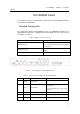
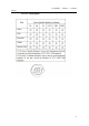
DS-3D2208P Hardware Installation Manual DS-3D2208P Switch The document describes the characteristics and parameters of DS-3D2208P and gives an overview of DS-3D2208P. Standard Configuration The standard port settings of DS-3D2208P consists of 8 100M-Ethernet RJ45 ports, 2 gigabit-Ethernet RJ45 ports, 2 gigabit-Ethernet SFP optical ports and 1 Console port. For details, see table 1-1.
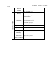
DS-3D2208P Hardware Installation Manual 6 LINK/ACT LED of the gigabit port 7 8 100M electrical ports 8 LEDs of 8 100M electrical ports If the LED is always on, the link on the port is normal. If the LEDs are always on, the links of LINK/ACT POE these ports are normal. If the PoE LED is on, the power has 8 PoE LEDs obtained the PoE power supply. Figure 0-2 Table 0-3 No. Back faceplate of the DS-3D2208P switch Parts at the back faceplate of the DS-3D2208P switch Abbrev.
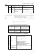
DS-3D2208P Hardware Installation Manual Network management standard Memory RFC 1157 SNMP v1/v2 RFC 1213 MIB II RFC 1757 RMON 1,2,3,9 EPROM: 512K Bytes Flash Memory: 8M Bytes SDRAM: 64MBytes Hardware characteristics Standard configuration 8 10/100BASE-T/PoE ports 2 10/100/1000 Base-T ports 2 1000M SFP optical ports One Console port Specifications 340mm*200mm*44mm Working temperature/humidit y 0℃-60℃; 10%-85% no condensation Storage temperature/ humidity -40℃-80℃; 5%-95% no condensation Power so
DS-3D2208P Hardware Installation Manual ROHS Description -4-
DS-3D2208P Hardware Installation Manual Installation Preparation Cautions Similar to other electronic products, the semiconductor chip easily gets damaged if you power on and off abruptly and frequently. To restart up the switch of DS-3D2208P, you have to open the power on-off three or five seconds after the power is cut off. Avoid severe collision or falling down from the height to protect the parts in the switch. Use correct outside ports to connect the switch of DS-3D2208P.
DS-3D2208P Hardware Installation Manual (11) Pull out the AC power socket and close the direct-current power before operating on the chassis or working beside the power source. (12) The final configuration of products must comply with relative national laws and regulations. Safety Principles for Live Working When you work under electricity, following the following principles: (13) Put off ornaments, such as ring, necklace, watch and bracelet, before you operate under live working.
DS-3D2208P Hardware Installation Manual Electrostatic Discharge Prevention Electrostatic discharge may damage devices and circuits. Improper treatment may cause the switch to malfunction completely or discontinuously. Move or locate the devices according to the measures of electrostatic discharge prevention, ensuring the chassis connects the ground. Another measure is to wear the static-proof hand ring.
DS-3D2208P Hardware Installation Manual (30) Ensure that nice ventilation is provided for the devices installed at the bottom of the cabinet. (31) The clapboard separates exhaust gas and inflow air, and boost the cool air to flow in the chassis. The best location of the clapboard is decided by the air flow mode in the chassis, which can be obtained through different location tests.
DS-3D2208P Hardware Installation Manual Installing the DS-3D2208P Switch Caution: Only professionals are allowed to install or replace the devices of the router. Installation Flow of DS-3D2208P Installing the Chassis of the Switch The chassis of the router can be installed on the desk or can be fixed to other cabinets. Your network installation requirements can be met if you conduct the operations according to the following procedure.
DS-3D2208P Hardware Installation Manual Installing the Machine Box on the Desk The DS-3D2208P switch can be directly put on the smooth and safe desk. Note: Do not put things weighing 4.5 kg or over 4.5 kg on the top of the switch. Installing the Chassis on the Cabinet The chassis of the switch is fixed on the cabinet through the brackets. When you fix the brackets, the front template of the switch faces forward. The detailed operations are shown in Figure 3-1.
DS-3D2208P Hardware Installation Manual a console cable, you can configure and monitor the switch of DS-3D2208P by running a terminal emulation software, such as super Windows terminal. The cable is provided according to the host. The communication parameters of the terminal serial port can be set to a rate of 9600bps, eight data bits, one stop bit, no sum check bit and traffic control. The RJ45 connector of the console port is shown in the following figure.
DS-3D2208P Hardware Installation Manual Note: The switch shown in the previous figure does not represent a real DS-3D2208P switch. Table 0-1 Definition of the pins of the UTP port No.
DS-3D2208P Hardware Installation Manual Figure 0-6 RJ-45 connector of the console port Because 8 10/100Base-T ports of DS-3D2208P support the MDI/MDIX auto-identification of the cable, DS-3D2208P can adopt five classes of direct-through/cross network cables when it connects other Ethernet terminals. Figure 0-7 Connecting the 10/100Base-T port and other Ethernet terminals Note: The switch shown in the previous figure does not represent a real DS-3D2208P switch.
DS-3D2208P Hardware Installation Manual 3 Receiving the normal phase of the data RX+ 6 Receiving the paraphase of the data RX- Connecting the 1000M-Ethernet Electric Port DS-3D2208P provides 2 10/100/1000MBase-T ports, each of which corresponds to an LED that shows the link/ACT state of each port. If the LED is always on, it means the port is linked. If the LED flickers, it means that the data is transmitted through the port.
DS-3D2208P Hardware Installation Manual paraphase of data 2 7 Sending and receiving the normal phase of data 3 TP3+ 8 Sending and receiving the paraphase of data 3 TP3- Connecting the 1000M Ethernet SFP Port DS-3D2208P provides 2 1000M SFP optical ports. You can insert the SFP module and then connect it to other Ethernet terminal devices through the optical fiber if you want to use the 1000M SFP port.
DS-3D2208P Hardware Installation Manual (44) Check whether the switch is correctly connected to other terminal devices.
DS-3D2208P Hardware Installation Manual Maintaining the Switch Caution: (46) Before opening the machine box, make sure that you have released the static you carried and then turn off the power on-off of the switch. Before operating any step in Appendix B, read the section “Safety Advice”. (47) Before performing operations beside the power source or on the chassis, turn off the power on-off and plug out the power cable.
DS-3D2208P Hardware Installation Manual (54) When the cover is opened, put it aside. The mainboard of the system appears. Note: After taking off the cover, put it horizontally and avoid it to be crushed or collided. Otherwise, the chassis is hard to install. Closing Chassis The section mainly describes how to put the cover and close the chassis. Do as follows: (1) Put them well according to their locations and joint them together along their sides. (2) See the following figure.
DS-3D2208P Hardware Installation Manual Hardware Fault Analysis The part describes how to remove the fault from the switch. Fault Separation The key for resolving the systematic faults is to separate the fault from the system. You can compare what the system is doing with what the system should do to detect the fault.
DS-3D2208P Hardware Installation Manual 1 PWR Power LED If the switch is powered on, the LED is on. If the LED is always on, the system is being started. 2 SYS System LED If the LED flickers, the system works normally. If the LED is always on, the link on the port is normal. 3 LINKACT LED at the top of each port If the LED is off, the port is not connected.