Digitaler Videorecorder Benutzerhandbuch UD.
User Manual of Digital Video Recorder Benutzerhandbuch COPYRIGHT ©2015 Hangzhou Hikvision Digital Technology Co., Ltd. ALLE RECHTE VORBEHALTEN. Alle Informationen, einschließlich Formulierungen, Bildern, Diagrammen, sind Eigentum von Hangzhou Hikvision Digital Technology Co., Ltd. oder seiner Tochtergesellschaften (nachfolgende "Hikvision").
User Manual of Digital Video Recorder BEI EINEM WIEDERSPRUCH ZWISCHEN DIESEM HANDBUCH UND GELTENDEM RECHT FINDET LETZTERES ANWENDUNG.
User Manual of Digital Video Recorder Hinweise zu Vorschriften und Richtlinien FCC-Information FCC-Konformität: Dieses Gerät wurde getestet und erfüllt die Grenzwerte für digitale Geräte gemäß Teil 15 der FCC-Vorschriften. Diese Grenzwerte sollen beim Betrieb des Geräts in einem gewerblichen Umfeld angemessenen Schutz gegen unerwünschte Störeinwirkungen bieten. Dieses Gerät erzeugt und verwendet Hochfrequenzenergie und kann diese abstrahlen.
User Manual of Digital Video Recorder Sicherheitshinweis Diese Hinweise sollen sicherstellen, dass der Benutzer das Produkt korrekt benutzen kann, um Gefahren oder Vermögensschäden zu vermeiden. Es gibt folgende Sicherheitshinweise: „Warnung“ und „Vorsicht“. Warnung: Bei Missachtung eines dieser Hinweise besteht die Gefahr von ernsthaften oder gar tödlichen Verletzungen. Vorsicht: Bei Missachtung eines dieser Hinweise besteht die Gefahr von Verletzungen oder Geräteschäden.
User Manual of Digital Video Recorder Vorbeugungs- und Warnhinweise Lesen Sie bitte aufmerksam die folgenden Hinweise, bevor Sie das Gerät anschließen und in Betrieb nehmen: • • • • • Achten Sie darauf, dass das Gerät in einer gut belüfteten, staubfreien Umgebung installiert ist. Das Gerät ist nur für den Betrieb im Innenbereich vorgesehen. Halten Sie das Gerät von Flüssigkeiten aller Art fern. Achten Sie darauf, dass die herstellerseitig vorgegebenen Umgebungsbedingungen erfüllt werden.
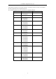
User Manual of Digital Video Recorder Vielen Dank für den Kauf unseres Produkts. Bei Fragen oder Anliegen wenden Sie sich bitte an den Händler. Die Werte im Handbuch dienen lediglich als Referenz. Dieses Handbuch gilt für die in der nachstehenden Liste aufgeführten Modelle.
User Manual of Digital Video Recorder Wesentliche Produktmerkmale Allgemein Anschließbar an HD-TVI- und analoge Kameras Anschließbar an Coaxitron-Kamera/Dome mit langer Übertragungsentfernung Anschließbar an IP-Kameras Der IP-Kameraanschluss wird nicht vom Modell DS-7100 unterstützt. Dual-Stream-Unterstützung durch jeden Kanal Der Main Stream unterstützt max. 1080P Auflösung, der Sub-Stream max. WD1 Auflösung Die Modelle DS-7100-E1 und DS-7200-E1/E2 unterstützen max.
User Manual of Digital Video Recorder HDD-Gruppenverwaltung HDD-Anteilsverwaltung; jedem Kanal kann eine andere Kapazität zugewiesen werden Aufzeichnung und Wiedergabe Konfigurierbarer Urlaubsaufnahmeplan Zyklische und nicht zyklische Aufnahmemodi Codierungsparameter für Normal- und Ereignisaufzeichnung Verschiedene Aufzeichnungsarten: Manuell, Kontinuierlich, Alarm, Bewegung, Bewegung | Alarm, Bewegung & Alarm und VCA Das Modell DS-7100 unterstützt keine VCA-gesteuerte Aufnahmeart.
User Manual of Digital Video Recorder Befugnisse festlegen, einschließlich der Zugriffsbeschränkung auf Kanäle Bedienung, Alarm, Ausnahmen sowie Protokollaufzeichnung und -suche Manuelles Auslösen und Löschen von Alarmen Importieren und Exportieren der Konfigurationsdatei von Geräten Automatischer Abruf des Kameratyps Netzwerkfunktionen 1 selbstadaptive selbstadaptive konfigurierbaren 10M/100M-Netzwerkschnittstelle beim 10M/100M/1000M-Netzwerkschnittstellen Betriebsmodi: Mehrfachadresse, D
User Manual of Digital Video Recorder Inhalt Wesentliche Produktmerkmale ................................................................................................................... 7 Chapter 1 Einführung.................................................................................................................................... 14 1.1 Frontblende.................................................................................................................................... 15 1.
User Manual of Digital Video Recorder 4.3 PTZ-Steuerung .............................................................................................................................. 78 Chapter 5 Aufzeichnungseinstellungen ........................................................................................................ 79 5.1 Konfigurieren der lokalen Parameter............................................................................................. 80 5.
User Manual of Digital Video Recorder 9.2.1 Extranet-Zugriff konfigurieren........................................................................................... 152 9.2.2 Konfigurieren der PPPoE-Einstellungen ............................................................................ 157 9.2.3 Konfigurierung der NTP Server-Einstellungen .................................................................. 158 9.2.4 Konfigurierung der SNMP-Einstellungen ............................................
User Manual of Digital Video Recorder 13.5 Verwalten von Benutzerkonten .................................................................................................... 205 13.5.1 Benutzer hinzufügen .......................................................................................................... 205 13.5.2 Benutzer löschen ................................................................................................................ 208 13.5.3 Benutzer bearbeiten ............................
User Manual of Digital Video Recorder Chapter 1 Einführung 14
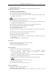
User Manual of Digital Video Recorder 1.1 Frontblende Figure 1. 1 Frontblende beim DS-7100 Table 1. 1 Beschreibung der Vorderseite Nr. Symbol Beschreibung 1 Leuchtet rot, wenn der DVR eingeschaltet ist. 2 Leuchtet rot, wenn Daten gelesen oder geschrieben werden. 3 Blinkt blau, wenn die Netzwerkverbindung korrekt funktioniert. Figure 1. 2 Vorderseite beim DS-7204/7208HGHI-SH Figure 1. 3 Vorderseite beim DS-7216HGHI-SH Abbildung 1.2 und Abbildung 1.3 zeigen die Vorderseite beim DS-7200HGHI-E1/E2.
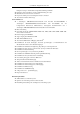
User Manual of Digital Video Recorder Nr. Bezeichnung Funktionsbeschreibung betätigt wird. STATUS Blinkt rot, wenn Daten gelesen oder geschrieben werden. Blinkt gelb, wenn die Netzwerkverbindung korrekt funktioniert. Tx/Rx 2 IR-Empfänger 3 USB-Schnittstellen Empfänger für die IR-Fernbedienung Universal Serial Bus (USB)-Ports für Zusatzgeräte wie USB-Maus und USB-Laufwerk (HDD). Figure 1. 4 Vorderseite beim DS-7200HQHI-SH Table 1. 3 Beschreibung der Vorderseite Nr.
User Manual of Digital Video Recorder Nr. Bezeichnung Funktionsbeschreibung Eingabe der Ziffer "5". Eingabe der Buchstaben "JKL". Löscht das Zeichen vor dem Cursor. 5/JKL/EDIT Markiert das Kontrollkästchen und wählt den EIN/AUS-Schalter. Startet/Stoppt das Beschneiden der Aufzeichnung im Wiedergabemodus. Eingabe der Ziffer "6". 6/MNO/PLAY Eingabe der Buchstaben "MNO". Im Wiedergabemodus wird mit ihr das Steuerungsmenü ein- und ausgeblendet. Eingabe der Ziffer "7". Eingabe der Buchstaben "PQRS".
User Manual of Digital Video Recorder Nr. Bezeichnung 4 USB-Schnittstelle 5 IR-Empfänger Funktionsbeschreibung Universal Serial Bus (USB)-Ports für Zusatzgeräte wie USB-Maus und USB-Laufwerk (HDD). Empfänger für die IR-Fernbedienung. Figure 1. 5 Vorderseite beim DS-7300HGHI-SH und DS-7300HQHI-SH Table 1. 4 Beschreibung der Vorderseite Nr. Bezeichnung Funktionsbeschreibung Leuchtet grün, wenn der DVR eingeschaltet ist.
User Manual of Digital Video Recorder Nr. Bezeichnung Funktionsbeschreibung die PTZ-LED ein-/ausgeschaltet; die Taste dient zum Auszoomen. In der Liveansicht oder im Wiedergabemodus kann mit ihr zwischen Haupt- und Spot-Videoausgang gewechselt werden. Eingabe der Ziffer "3". Eingabe der Buchstaben "DEF". 3/DEF/F2 Die Taste F2 dient dazu, die Registerseiten zu wechseln. Im PTZ-Steuerungsmodus dient sie zum Einzoomen des Bilds. Eingabe der Ziffer "4". 4/GHI/ESC Eingabe der Buchstaben "GHI".
User Manual of Digital Video Recorder Nr. Bezeichnung Funktionsbeschreibung Im PTZ-Steuermodus dient sie zum Steuern der PTZ-Kamera. Die EINGABETASTE dient dazu, eine in den Menüs getroffene Auswahl zu bestätigen. Sie kann auch benutzt werden, um Kontrollkästchen zu markieren. EINGABETASTE Im Wiedergabemodus kann sie benutzt werden, um die Videowiedergabe zu starten oder anzuhalten. Wenn sie im Einzelwiedergabemodus gedrückt wird, geht das Video ein Einzelbild weiter.
User Manual of Digital Video Recorder Nr. Bezeichnung GUARD Funktionsbeschreibung Leuchtet blau, wenn das Gerät unscharfgeschaltet ist. Leuchtet nicht, wenn das Gerät scharfgeschaltet ist. Der Scharf/Unscharf-Status kann aktiviert werden, indem man die ESC-Taste in der Liveansicht länger als drei Sekunden lang gedrückt hält. Schaltet den entsprechenden Kanal in der Liveansicht oder im PTZ-Steuermodus. Dient zum Eingeben von Zahlen und Buchstaben im Kanälen im Bearbeitungsmodus.
User Manual of Digital Video Recorder Nr. Bezeichnung nstasten Funktionsbeschreibung Ruft das Konfigurierungsmenüfür manuelle Aufzeichnungen auf. In PTZ-Steuerungseinstellungen kann über die Taste REC in REC/SHOT Verbindung mit einer Zifferntaste ein PTZ-Preset abgerufen werden. Sie dient auch dazu, die Audiofunktion im Wiedergabemodus einund auszuschalten. Ruft das Wiedergabemenüauf. PLAY/AUTO ZOOM+ Auto-Scan-Funktion im PTZ-Steuermodus. Zoom die Kamera in den PTZ-Steuerungseinstellungen ein.
User Manual of Digital Video Recorder Figure 1. 7 Vorderseite beim DS-9000HQHI-SH Table 1. 6 Beschreibung der Bedientasten Nr. Bezeichnung ALARM READY Funktionsbeschreibung Die Alarmanzeige leuchtet rot, wenn ein Sensoralarm festgestellt wird. Die Bereitschaftsanzeige leuchtet im Normalbetrieb blau als Hinweis darauf, dass das Gerät einwandfrei funktioniert.
User Manual of Digital Video Recorder aktivieren/deaktivieren. Ruft das Konfigurierungsmenüfür manuelle Aufzeichnungen auf. In PTZ-Steuerungseinstellungen kann über die Taste REC in Verbindung REC/SHOT mit einer Zifferntaste ein PTZ-Preset abgerufen werden. Sie dient auch dazu, die Audiofunktion im Wiedergabemodus ein- und auszuschalten. PLAY/AUTO ZOOM+ Dient dazu, den Wiedergabemodus zu aktivieren. Aktiviert ferner die Auto Scan-Funktion im PTZ-Steuerungsmenü.
User Manual of Digital Video Recorder Im Wiedergabemodus dienen die Tasten "Auf" und "Ab" dazu, die Geschwindigkeit der Videowiedergabe zu erhöhen oder zu verringern. Die Tasten "Links" und "Rechts" dienen dazu, den nächsten oder vorhergehenden Tag mit Aufzeichnungen auszuwählen. Im Liveansicht-Modus kann man mit diesen Tasten die Kanäle wechseln. Im PTZ-Steuermodus dient sie zum Steuern der PTZ-Kamera. Die EINGABETASTE dient dazu, eine in den Menüs getroffene Auswahl zu bestätigen.
User Manual of Digital Video Recorder 1.2 Steuerung per IR-Fernbedienung Der DVR kann auch mit Hilfe der mitgelieferten Fernbedienung (siehe Figure 1. 8) gesteuert werden. Vor der Inbetriebnahme müssen Batterien (2×AAA) eingesetzt werden. Figure 1. 8 Fernbedienung Die Tasten entsprechen in ihrer Funktionsweise weitgehend denen auf der Gerätevorderseite. Siehe Table 1. 7: Table 1. 7 Beschreibung der IR-Fernbedienungstasten Nr. Bezeichnung Beschreibung Schaltet das Gerät ein/aus.
User Manual of Digital Video Recorder Nr. Bezeichnung Beschreibung Ruft das Konfigurierungsmenüfür manuelle Aufzeichnungen auf. In PTZ-Steuerungseinstellungen kann über die Taste REC in Verbindung 3 Taste REC mit einer Zifferntaste ein PTZ-Preset abgerufen werden. Sie dient auch dazu, die Audiofunktion im Wiedergabemodus ein- und auszuschalten. Dienen zum Navigieren zwischen verschiedenen Feldern und Menüelementen.
User Manual of Digital Video Recorder > Weitere Einstellungen". 2. Überprüfen und merken Sie sich die DVR-Nummer. Standardmäßig lautet die DVR-Nr. "255". Diese Geräte-ID gilt für alle IR-Fernbedienungen. 3. Betätigen Sie die Taste "DEV" auf der Fernbedienung. 4. Geben Sie die Geräte-ID aus Schritt 2 ein. 5. Betätigen Sie die Taste "ENTER" auf der Fernbedienung. Wenn die Status-LED auf der Gerätevorderseite blau leuchtet, funktioniert die Fernbedienung einwandfrei.
User Manual of Digital Video Recorder 1.3 Bedienung per USB-Maus Dieser DVR kann auch mit einer handelsüblichen 3-Tasten-USB-Maus (Links/Rechts/Scroll-Rad) bedient werden. So benutzen Sie die USB-Maus: Schritte: 1. Schließen Sie die Maus am USB-Port auf der Gerätevorderseite an. 2. Die Maus sollte automatisch erkannt werden. Falls, wie in seltenen Fällen möglich, die Maus nicht erkannt wird, sind die beiden Geräte unter Umständen nicht miteinander kompatibel.
User Manual of Digital Video Recorder 1.4 Eingabemethode Figure 1. 9 Virtuelle Tastatur Beschreibung der Tasten auf der virtuellen Tastatur: Table 1.
User Manual of Digital Video Recorder 1.5 Rückseite Die Geräterückseite variiert je nach Modell. Informieren Sie sich bitte am jeweiligen Produkt. Die nachstehenden Abbildungen dienen lediglich zur Veranschaulichung. Figure 1. 10 DS-7100 Table 1. 10 Beschreibung der Rückseite Nr. Element Beschreibung 1 VIDEO IN BNC-Anschluss zur analogen Videoeingabe 2 HDMI HDMI-Videoausgang 3 VGA DB15-Anschluss zur VGA-Ausgabe.
User Manual of Digital Video Recorder und Menü. 5 HDMI HDMI-Videoausgang 6 USB-Port Universeller serieller Bus-Port für zusätzliche Geräte 7 Netzwerkschnittstelle Netzwerkanschluss 8 RS-485-Schnittstelle Anschluss für RS-485-Geräte 9 Stromversorgung 12-V-Gleichstromversorgung 10 Ein/Aus-Schalter Dient zum Ein- und Ausschalten des Geräts 11 GND Masse 12 Alarm Ein/Aus (nur Anschlüsse für Alarmeingangs- und -ausgangssignale DS-7200HQHI-SH) Figure 1.
User Manual of Digital Video Recorder Figure 1. 16 DS-8132HGHI-SH Figure 1. 17 DS-8100/9000HQHI-SH Table 1. 12 Beschreibung der Rückseite Nr. Element Beschreibung 1 VIDEO IN BNC-Anschluss zur analogen Videoeingabe VIDEO OUT BNC-Anschluss zur Videoausgabe. 2 Die Modelle DS-7324/7332HGHI-SH und DS-8124/8132HGHI-SH haben keinen CVBS-Ausgang.
User Manual of Digital Video Recorder Nr. Element Beschreibung 12 GND Masse 13 LINE IN BNC-Anschluss zur Audioeingabe.
User Manual of Digital Video Recorder Chapter 2 Erste Schritte 35
User Manual of Digital Video Recorder 2.1 Ein- und Ausschalten des DVR Zweck: Für eine maximale Gerätelebensdauer ist die Beachtung der korrekten Ein- und Ausschaltverfahren ganz wesentlich. Bevor Sie anfangen: Überprüfen Sie, ob des Spannung der Zusatznetzteils den Anforderungen des Geräts entspricht und die Erdung korrekt vorgenommen wurde. DVR einschalten Schritte: 1. Kontrollieren Sie, ob das Netzteil an einer Steckdose angeschlossen ist.
User Manual of Digital Video Recorder 2. Geben Sie zur Authentifizierung den Administratornamen und das Kennwort im Dialogfeld ein. 3. Klicken Sie auf Ja. Drücken Sie die EIN/AUS-Taste nicht erneut, solange der Abschaltvorgang läuft. Nach dem Abschalten bleibt das Gerät im Standby-Modus, und die EIN/AUS-Taste leuchtet rot. Um das Gerät wieder einzuschalten, drücken Sie die EIN/AUS-Taste auf der Fernbedienung. DVR neu starten Im Menü"Herunterfahren" (Figure 2. 1) können Sie den DVR auch neu starten.
User Manual of Digital Video Recorder 2.2 Einrichten des Administratorkennworts Zweck: Beim erstmaligen Zugriff müssen Sie das Gerät durch Einrichten eines Administratorkennworts aktivieren. Vorher ist kein Betrieb möglich. Sie können das Gerät auch über einen Webbrowser, SADP oder die Client-Software aktivieren. Schritte: 1. Geben Sie im Textfeld Neues Kennwort erstellen und Neues Kennwort bestätigen jeweils dasselbe Kennwort ein. Figure 2.
User Manual of Digital Video Recorder Figure 2.
User Manual of Digital Video Recorder 2.3 Basiskonfigurierung mittels Assistenten Standardmäßig erscheint der Assistent, wenn das Gerät geladen wurde. Figure 2. 5 Dialog zum Starten des Assistenten Benutzung des Konfigurationsassistenten: 1. Dieser Assistent leitet Sie durch einige wichtige Einstellungen des DVR. Falls Sie den Assistenten momentan nicht benutzen möchten, klicken Sie auf Beenden.
User Manual of Digital Video Recorder Figure 2. 7 Allgemeine Netzwerkkonfiguration 1 selbstadaptive 10M/100M-Netzwerkschnittstelle beim DS-7100, DS-7204/7208HGHI-SH und DS-7200HGHI-E1/E2; 2 selbstadaptive 10M/100M/1000M-Netzwerkschnittstellen beim DS-8100HQHI und HGHI-SH mit drei konfigurierbaren Betriebsmodi: Mehrfachadresse, Lastausgleich, Netzfehlertoleranz, und 1 selbstadaptive 10M/100M/1000M-Netzwerkschnittstelle bei anderen Modellen 4.
User Manual of Digital Video Recorder Figure 2. 9 HDD-Verwaltung 7. Um die HDD zu initialisieren, klicken Sie auf Initialisieren. Bei der Initialisierung werden sämtliche auf der HDD gespeicherten Daten gelöscht. 8. Klicken Sie auf Weiter, um den Dialog IP-Kameraverwaltung aufzurufen (nur von der HDVR-Reihe unterstützt). 9. Klicken Sie auf Suchen, um die Online-IP-Kamera zu suchen. Der Status Sicherheit gibt an, ob sie aktiv oder inaktiv ist.
User Manual of Digital Video Recorder Figure 2. 11 Aufzeichnungseinstellungen 12. Klicken Sie auf OK, um den Konfigurationsassistenten zu beenden.
User Manual of Digital Video Recorder 2.4 Anmeldung und Abmeldung 2.4.1 Benutzeranmeldung Zweck: Wenn der DVR abgemeldet wurde, müssen Sie ihn erst wieder anmelden, bevor Sie auf das Menüund andere Funktionen zugreifen können. Schritte: 1. Wählen Sie den Benutzernamen in der Auswahlliste. Figure 2. 12 Anmeldedialog 2. Geben Sie das Kennwort ein. 3. Klicken Sie auf OK, um sich anzumelden.
User Manual of Digital Video Recorder Figure 2. 14 Abmelden 2. Klicken Sie auf Abmelden. Nachdem Sie sich vom System abgemeldet haben, ist keine Menübedienung auf dem Bildschirm mehr möglich. Um das System zu entsperren, müssen Sie sich erst wieder mit Benutzernamen und Kennwort anmelden.
User Manual of Digital Video Recorder 2.5 IP-Kameras hinzufügen und verbinden Dieser Abschnitt ist beim DVR-Modell DS-7100 nicht verfügbar. 2.5.1 Administratorkennwort für die IP-Kamera einrichten Zweck: Achten Sie vor dem Hinzufügen der IP-Kamera darauf, dass sie sich im aktiven Betriebszustand befindet. Schritte: 1. Öffnen Sie in der Liveansicht per Rechtsklick das Kontextmenü und wählen Sie die Option IP-Kamera hinzufügen oder rufen Sie unter "Menü> Kamera > Kamera" die IP-Kameraverwaltung auf.
User Manual of Digital Video Recorder Figure 2. 16 Kameraaktivierung 3. Richten Sie das Kennwort für die Kamera ein, um sie zu aktivieren. Administratorkennwort benutzen: Wenn Sie ein Kontrollkästchen markieren, wird die Kamera mit demselben Administratorkennwort wie der entsprechende DVR konfiguriert. Figure 2. 17 Neues Kennwort einrichten Neues Kennwort einrichten: Falls das Administratorkennwort nicht benutzt wird, müssen Sie ein neues Kennwort für die Kamera einrichten und es bestätigen.
User Manual of Digital Video Recorder OPTION 1: Schritte: 1. Öffnen Sie in der Liveansicht per Rechtsklick das Kontextmenü und wählen Sie die Option IP-Kamera hinzufügen oder rufen Sie unter "Menü> Kamera > Kamera" die IP-Kameraverwaltung auf. Figure 2. 18 Anmeldedialog für IP-Kameras 2. Online-Kameras im selben Netzwerksegment werden erkannt und in der Kameraliste angezeigt. 3.
User Manual of Digital Video Recorder OPTION 2: Schritte: 1) Klicken Sie in der IP-Kameraverwaltung auf Benutzerdefiniertes Hinzufügen, um den Dialog "IP-Kamera hinzufügen (benutzerdefiniert)" aufzurufen. Figure 2. 20 Benutzerdefinierte Hinzufügung von IP-Kameras 2) Hier können Sie IP-Adresse, Protokoll, Verwaltungsport und sonstige Informationen zur betreffenden IP-Kamera eingeben.
User Manual of Digital Video Recorder Beim DVR-Modell DS-7200 können 1-Kanal- oder 2-Kanal-IP-Kameras hinzugefügt werden; bei den DVR-Modellen DS-7300/8100/9000 kann eine weitere IP-Kamera hinzugefügt werden, indem man einen Analogkanal deaktiviert, und es können bis zu 32 IP-Kameras hinzugefügt werden. Die nachstehende Tabelle bietet eine Übersicht über die Anzahl anschließbarer IP-Kameras je nach Modell. Table 2.
User Manual of Digital Video Recorder Eine Liste kompatibler IP-Kameras finden Sie im Anhang. Table 2. 2 Erklärung der Symbole Symbol Erklärung Symbol Basisparameter der Kamera Erklärung Erkannte IP-Kamera hinzufügen konfigurieren Die Kamera ist nicht angeschlossen. Klicken Sie auf das Symbol, um die Ausnahmeinformation für IP-Kamera löschen die Kamera zu erhalten.
User Manual of Digital Video Recorder 2. Klicken Sie auf OK, um die Einstellungen zu speichern und den Bearbeitungsdialog zu beenden. So bearbeiten Sie weiterführende Parameter: 1. Ziehen Sie die horizontale Bildlaufleiste nach rechts und klicken Sie auf das Symbol . Figure 2. 23 Netzwerkkonfiguration der Kamera 2. Sie können die Netzwerkinformationen und das Kennwort der Kamera bearbeiten. Figure 2. 24 Kennwortkonfiguration der Kamera 3.
User Manual of Digital Video Recorder Figure 2. 25 Protokollverwaltungsdialog Es gibt 16 benutzerdefinierte Protokolle im System, bei denen Sie den Protokollnamen bearbeiten und festlegen können, ob der Sub-Stream aktiviert werden soll. 2. Wählen Sie den Übertragungstyp und die Übertragungsprotokolle. Bevor Sie das Protokoll für die Netzwerkkamera festlegen, müssen Sie sich beim Kamerahersteller nach der URL (Uniform Resource Locator) zum Abrufen von Main Stream und Sub-Stream erkundigen.
User Manual of Digital Video Recorder Figure 2. 26 Protokolleinstellungen 3. Wählen Sie die soeben hinzugefügten Protokolle, um den Anschluss der Netzwerkkamera zu überprüfen.
User Manual of Digital Video Recorder Chapter 3 Liveansicht 55
User Manual of Digital Video Recorder 3.1 Einführung in die Liveansicht In der Liveansicht sehen Sie das Videobild jeder Kamera in Echtzeit. Beim Einschalten wechselt der DVR automatisch in den Liveansicht-Modus. Da dies auch die oberste Menüebene darstellt, kommen Sie durch wiederholtes Betätigen der Taste "ESC" (je nach Menü) stets wieder zurück zur Liveansicht.
User Manual of Digital Video Recorder 3.2 Bedienung im Liveansicht-Modus In der Liveansicht sind die nachstehend aufgeführten Funktionen verfügbar. • Einzelbildschirm: Es wird nur ein Bildschirm auf dem Monitor angezeigt. • Mehrfachbildschirm: Es werden mehrere Bildschirme gleichzeitig auf dem Monitor angezeigt. • Autom. Umschaltung: Es wird automatisch von einem Bildschirm zum nächsten gewechselt.
User Manual of Digital Video Recorder √ bedeutet, dass die Schnittstelle benutzt wird, × bedeutet, dass sie nicht benutzt wird oder nicht keine Verbindung besteht. HDMI, VGA und CVBS können gleichzeitig benutzt werden. Sonstige Modelle Bei den übrigen Modellen lautet der Prioritätslevel: HDMI > VGA > CVBS. Siehe Tabelle unten. Table 3. 4 Prioritäten der Schnittstellen S.N.
User Manual of Digital Video Recorder Bildschirm Nächster Bildschirm Wechselt zum nächsten Bildschirm Sequenzanzeige Aktiviert/Deaktiviert die automatische Bildschirmumschaltung starten/beenden Die Verweildauer der Liveansicht-Konfiguration muss zuvor unter Automatische Umschaltung starten definiert werden. Aufzeichnung starten Startet die Aufzeichnung aller Kanäle; in der Auswahlliste kann zwischen normaler Aufnahme und Bewegungserkennungsaufnahme gewählt werden.
User Manual of Digital Video Recorder 3.2.3 Haupt-/Zusatzausgang-Umschaltung Die Modelle DS-7100-SH, DS-7200-SH und DS-7324/7332HGHI-SH unterstützten diese Funktion nicht. Wenn der HDMI-, HDMI/VGA- oder HDMI1/VGA (DS-8124/8132HGHI-SH)-Ausgang als Hauptausgang konfiguriert ist, können Sie folgende Funktionen nutzen, um zum CVBS-, VGA- oder HDMI2 (DS-8124/8132HGHI-SH)-Ausgang als Hauptausgang umzuschalten. Schritte: 1. Klicken Sie mit der rechten Maustaste den HDMI (1)/VGA-Ausgangsbildschirm doppelt an.
User Manual of Digital Video Recorder aktivieren/deaktiv ieren PTZ-Steuerung Digitaler Zoom Bildeinstellungen Aktuelle Liveansicht-Strate Liveansicht gie schließen Bei der Sofortwiedergabe werden nur die letzten fünf Minuten der Aufzeichnung wiedergegeben. Falls keine Aufnahme gefunden wird, bedeutet das, dass in den letzten fünf Minuten keine Aufzeichnung erfolgte. Mit dem digitalen Zoom kann der gewählte Bereich als Vollbild dargestellt werden.
User Manual of Digital Video Recorder Figure 3. 5 Bildeinstellungen Hier können Sie Bildparameter wie Helligkeit, Kontrast, Sättigung und Farbton, Schärfe und Entrauschen einstellen. Klicken Sie auf Standard, um die Standardvorgaben wiederherzustellen, und auf Kopieren, um die Bildeinstellungen für andre Analogkameras zu übernehmen. Zu Einzelheiten siehe Kapitel 11.3 Videoparameter konfigurieren. Liveansicht-Strategie mit den Optionen "Echtzeit", "Ausgewogen" und "Flüssigkeit" Figure 3.
User Manual of Digital Video Recorder 3.3 Kanal-Null-Codierung Dieses Kapitel gilt nicht für die DVR-Modelle DS-7100 und DS-7200. Zweck: Manchmal ist es erforderlich, eine Fernansicht mehrerer Kanäle in Echtzeit vom Webbrowser oder der CMS (Client Management System)-Software zu bekommen, um die Bandbreitenanforderungen zu verringern, ohne die Bildqualität zu beeinträchtigen. Als Option für Sie wird die Kanal-Null-Codierung unterstützt. Schritte: 1.
User Manual of Digital Video Recorder 3.4 Liveansicht-Einstellungen anpassen Zweck: Die Einstellungen der Liveansicht können an die jeweiligen Anforderungen angepasst werden. Konfigurierbar sind beispielsweise Ausgabeschnittstelle, Verweilzeit des angezeigten Bildschirms, Ton ein/aus, Anzahl der Bildschirme pro Kanal usw. Schritte: 1. Rufen Sie den Konfigurierungsdialog für die Liveansicht auf: Menü> Konfiguration > Liveansicht Figure 3.
User Manual of Digital Video Recorder Figure 3. 9 Liveansicht – Kamerareihenfolge 2) Klicken Sie ein Fenster an, um es auszuwählen, und klicken Sie dann in der Liste doppelt auf den Namen der Kamera, die angezeigt werden soll. "X" bedeutet, dass der Kanal keine Kamera anzeigt. 3) Klicken Sie auf , um der Reihe nach die Liveansicht aller Kanäle zu starten, und auf Liveansicht aller Kanäle zu stoppen. Klicken Sie auf nächsten Seite zu gelangen. 4) Klicken Sie auf Anwenden.
User Manual of Digital Video Recorder 3.5 Manuelle Videoqualitätsdiagnose Zweck: Die Videoqualität der analogen Kanäle kann manuell ermittelt und als Liste mit Diagnoseergebnissen angezeigt werden. Schritte: 1. Rufen Sie den Dialog Manuelle Videoqualitätsdiagnose auf. Menü> Manuell > Manuelle Videoqualitätsdiagnose Figure 3. 10 Videoqualitätsdiagnose 2. Markieren Sie die Kontrollkästchen der zu diagnostizierenden Kanäle. 3. Klicken Sie auf Diagnose, um eine Ergebnisliste zu erstellen.
User Manual of Digital Video Recorder 3.6 Benutzerabmeldung Zweck: Nach der Abmeldung kehrt der Monitor in den Liveansichtsmodus zurück. Um erneut Vorgänge durchzuführen, müssen Sie sich wieder mit Ihrem Benutzernamen und Ihrem Kennwort anmelden. Schritte: 3. Rufen Sie das Menü"Herunterfahren" auf. Menü> Herunterfahren Figure 3. 12 Herunterfahren 4. Klicken Sie auf Abmelden.
User Manual of Digital Video Recorder Chapter 4 PTZ-Steuerung 68
User Manual of Digital Video Recorder 4.1 Konfigurierung der PTZ-Parameter Zweck: Führen Sie die nachstehenden Schritte aus, um die Parameter für die PTZ-Steuerung zu konfigurieren. Die PTZ-Parameter müssen konfiguriert werden, bevor Sie die PTZ-Kamera steuern können. Schritte: 1. Rufen Sie den Konfigurierungsdialog für die PTZ-Steuerung auf: Menü> Kamera > PTZ Figure 4. 1 PTZ-Einstellungen 2. Wählen Sie in der Auswahlliste Kamera die gewünschte Kamera für die PTZ-Einstellung. 3.
User Manual of Digital Video Recorder Für die angeschlossene Coaxitron-Kamera (Dome) können Sie als PTZ-Protokoll "HIKVISION-C (Coaxitron)" wählen. Achten Sie darauf, dass das gewählte Protokoll von der angeschlossenen Kamera (Dome) unterstützt wird. Bei Auswahl des Coaxitron-Protokolls sind alle anderen Parameter wie Baudrate, Datenbit, Stoppbit, Parität und Flusssteuerung nicht konfigurierbar. 5. Klicken Sie auf Anwenden, um die Einstellungen zu speichern.
User Manual of Digital Video Recorder 4.2 Konfigurierung von PTZ-Presets, Patrouillen und Mustern Bevor Sie anfangen: Achten Sie bitte darauf, dass die Presets, Patrouillen und Muster von den PTZ-Protokollen unterstützt werden. 4.2.1 Benutzerdefinierte Presets Zweck: Befolgen Sie die Schritte zum Einstellen des Preset-Punkts, auf den die PTZ-Kamera beim Eintreten eines Ereignisses gerichtet werden soll. Schritte: 1. Rufen Sie die PTZ-Steuerung auf: Menü> Kamera > PTZ Figure 4. 3 PTZ-Einstellungen 2.
User Manual of Digital Video Recorder Diese Funktion ermöglicht es, die Kamera beim Eintreten eines Ereignisses in eine zuvor festgelegte Szene (z. B. ein Fenster) zu richten. Schritte: 1. Klicken Sie unten rechts in den PTZ-Einstellungen auf PTZ. Alternativ drücken Sie die PTZ-Taste auf der Gerätevorderseite, oder Sie klicken auf das PTZ-Steuerungssymbol in der Symbolleiste, oder Sie wählen die PTZ-Option im Kontextmenü, um die PTZ-Steuerung aufzurufen. 2.
User Manual of Digital Video Recorder Figure 4. 5 PTZ-Einstellungen 2. Wählen Sie in der Auswahlliste die Patrouillennummer. 3. Klicken Sie auf Einstellen, um die KeyPoints für die Patrouille hinzuzufügen. Figure 4. 6 KeyPoint-Konfiguration 4. Konfigurieren Sie die KeyPoint-Parameter wie KeyPoint-Nr., Verweildauer und Patrouillengeschwindigkeit. Der KeyPoint entspricht dem Preset. KeyPoint-Nr.: Legt die Reihenfolge für die PTZ-Steuerung während der Patrouille fest.
User Manual of Digital Video Recorder die PTZ-Steuerung aufzurufen. 2. Klicken Sie auf , um die Grundeinstellungen der PTZ-Steuerung anzuzeigen. Figure 4. 7 PTZ-Steuerung – Allgemein 3. Wählen Sie eine Patrouille in der Auswahlliste und klicken Sie dann auf Patrouille aufrufen, um sie zu aktivieren. 4. Klicken Sie auf Patrouille stoppen, um sie zu stoppen. 4.2.5 Benutzerdefinierte Muster Zweck: Muster können eingerichtet werden, indem man die Bewegung der PTZ-Steuerung aufzeichnet.
User Manual of Digital Video Recorder 4.2.6 Muster aufrufen Zweck: Führen Sie die folgenden Schritte aus, damit sich die PTZ-Kamera entsprechend den vorgegebenen Mustern bewegt. Schritte: 1. Klicken Sie unten rechts in den PTZ-Einstellungen auf PTZ. Alternativ drücken Sie die PTZ-Taste auf der Gerätevorderseite, oder Sie klicken auf das PTZ-Steuerungssymbol in der Symbolleiste, oder Sie wählen die PTZ-Option im Kontextmenü, um die PTZ-Steuerung aufzurufen. 2.
User Manual of Digital Video Recorder Figure 4. 10 PTZ-Einstellungen 2. Richten Sie die Kamera mit Hilfe der Pfeiltasten auf den Punkt, der die Grenze markieren soll, und klicken Sie dann auf Linke Begrenzung oder Rechte Begrenzung, um den Punkt mit der entsprechenden Begrenzung zu verknüpfen. Die Speed Dome-Kamera startet den linearen Scan-Vorgang von der linken zur rechten Begrenzung.
User Manual of Digital Video Recorder 3. Klicken Sie auf Lineare Begrenzung, um den linearen Scan-Vorgang zu starten; klicken Sie erneut, um ihn wieder zu stoppen. Klicken Sie auf Wiederherstellen, um die definierte linke und rechte Begrenzung zu löschen. Anschließend muss die Kamera neu gestartet werden, um die Änderungen zu übernehmen. 4.2.
User Manual of Digital Video Recorder 4.3 PTZ-Steuerung Es gibt zwei Möglichkeiten, die PTZ-Steuerung aufzurufen. OPTION 1: Klicken Sie in den PTZ-Einstellungen unten rechts (neben "Zurück") auf PTZ. OPTION 2: Betätigen Sie in der Liveansicht die PTZ-Steuerungstaste auf der Gerätevorderseite oder der IR-Fernbedienung, oder klicken Sie auf das PTZ-Steuerungssymbol , oder wählen Sie die PTZ-Option im Kontextmenü. Klicken Sie in der Systemsteuerung auf Konfiguration, um die PTZ-Einstellungen aufzurufen.
User Manual of Digital Video Recorder Chapter 5 Aufzeichnungseinstellungen 79
User Manual of Digital Video Recorder 5.1 Konfigurieren der lokalen Parameter Bevor Sie anfangen: 1. Achten Sie darauf, dass die HDD bereits installiert ist. Falls nicht, tun Sie dies bitte und initialisieren sie dann. (Menü> HDD > Allgemein) Figure 5. 1 HDD – Allgemein 2. Klicken Sie auf Weiterführend, um den Speichermodus für die HDD zu überprüfen. 1) Falls der HDD-Modus Anteil ist, stellen Sie bitte die maximale Aufnahme- und Bildkapazität ein. Ausführliche Hinweise hierzu enthält Kapitel 10.
User Manual of Digital Video Recorder 1) Wählen Sie das Register Aufzeichnung. 2) Wählen Sie eine Kamera in der Kameraliste. Je nach Bedarf können Sie den Streamtyp, die Auflösung, die Videoqualität und andere Parameter für Main-Stream (Dauer) bzw. Main-Stream (Ereignis) konfigurieren. Die Eingangsauflösung der angeschlossenen Kamera wird in der Liveansicht fünf Sekunden lang angezeigt, wenn die Kamera angeschlossen oder der DVR eingeschaltet wird.
User Manual of Digital Video Recorder Figure 5. 4 Kameraeinstellungen kopieren 3. Legen Sie die Codierungsparameter für den Sub-Stream fest. 1) Wählen Sie das Register Sub-Stream. Figure 5. 5 Sub-Stream-Codierung 2) Wählen Sie eine Kamera in der Kameraliste. 3) Konfigurieren Sie die Parameter. 4) Klicken Sie auf Anwenden, um die Einstellungen zu speichern. 5) (Optional) Klicken Sie auf Kopieren, um die Einstellungen auch für andere Kanäle zu übernehmen.
User Manual of Digital Video Recorder 5.2 Konfigurieren eines Aufzeichnungszeitplans Die Modelle DS-7100 unterstützen nur die Aufnahmeart "Kontinuierlich" und "Bewegung"; das Modell DS-7200HGHI unterstützt die Aufnahmearten "Kontinuierlich", "Bewegung" und "VCA"; alle anderen Modelle unterstützen die Aufnahmearten "Kontinuierlich", "Alarm", "Bewegung", "Bewegung | Alarm", "Bewegung & Alarm" und "VCA".
User Manual of Digital Video Recorder 3. Markieren Sie das Kontrollkästchen vor "Zeitplan aktivieren". 4. Konfigurieren Sie den Aufnahmezeitplan. Zeitplan bearbeiten 1) 2) 3) Klicken Sie auf Bearbeiten. Wählen Sie im Bearbeitungsdialog den gewünschten Tag. Um eine ganztägige Aufzeichnung zu planen, markieren Sie das Kontrollkästchen hinter Ganztägig. Figure 5.
User Manual of Digital Video Recorder Die Option Urlaub ist verfügbar, wenn Sie unter Urlaubseinstellungen die entsprechende Funktion aktiviert haben. Siehe Kapitel 5.7 Konfigurierung von Urlaubsaufzeichnungen. 5) Klicken Sie auf OK, um die Einstellungen zu speichern und zur übergeordneten Menüebene zu wechseln. Zeitplan per "Drag-and-Drop" einrichten 1) Klicken Sie auf das Farbsymbol, um in der Ereignisliste rechts eine Aufnahmeart auszuwählen. Figure 5.
User Manual of Digital Video Recorder 5.3 Konfigurierung einer Bewegungsaufzeichnung Zweck: Führen Sie die folgenden Schritte aus, um die Parameter für die Bewegungserkennung zu konfigurieren. Sollten im Liveansichtsmodus Bewegungsereignisse eintreten, können diese vom DVR analysiert und entsprechende Maßnahmen eingeleitet werden.
User Manual of Digital Video Recorder Figure 5. 14 Bewegungserkennungseinstellungen 5) Wählen Sie die Kanäle, auf denen bei einem Bewegungserkennungsereignis die Aufzeichnung ausgelöst werden soll. 6) Klicken Sie auf Anwenden, um die Einstellungen zu speichern. 7) Klicken Sie auf OK, um zur übergeordneten Menüebene zu wechseln. 8) Beenden Sie den Konfigurierungsdialog für die Bewegungserkennung. 3. Konfigurieren des Aufnahmezeitplans Bei Auswahl von "Bewegung" als Aufnahmeart siehe Schritt 4 in Kapitel 5.
User Manual of Digital Video Recorder 5.4 Konfigurieren einer alarmgesteuerten Aufzeichnung Die Modelle DS-7100 und DS-7200 unterstützen keinen Alarmeingang. Zweck: Befolgen Sie die Schritte unten, um eine alarmgesteuerte Aufzeichnung zu konfigurieren. Schritte: 1. Rufen Sie den Konfigurierungsdialog für die Alarmaufzeichnung auf: Menü> Konfiguration > Alarm Figure 5. 15 Alarmeinstellungen 2. Klicken Sie auf das Register Alarmeingang. Figure 5.
User Manual of Digital Video Recorder 5) Wählen Sie den Kanal für die alarmgesteuerte Aufzeichnung. 6) Markieren Sie das Kontrollkästchen 7) Klicken Sie auf Anwenden, um die Einstellungen zu speichern. 8) Klicken Sie auf OK, um zur übergeordneten Menüebene zu wechseln. , um den Kanal auszuwählen. Wiederholen Sie die Schritte oben, um weitere Alarmeingangsparameter zu konfigurieren.
User Manual of Digital Video Recorder 5.5 Konfigurieren einer VCA-Aufzeichnung Zweck: Die Modelle DS-7200/7300/8100/9000 unterstützen die VCA-gesteuerte Aufzeichnung (Linienüberquerungsund Einbrucherkennung). Die VCA-Einstellungen und die ereignisgesteuerte VCA-Aufzeichnung wird bei den Modellen DS-7200/7300/8100HGHI von einer analogen Kamera und bei den Modellen DS-7200/7300/8100/9000HQHI von zwei analogen Kameras unterstützt. Der DS-7100-SH unterstützt kein VCA. Schritte: 1.
User Manual of Digital Video Recorder Figure 5. 20 Triggerkanal für VCA-Alarm konfigurieren Die PTZ-Verknüpfungsfunktion ist nur bei den VCA-Einstellungen von IP-Kameras verfügbar. 4. Rufen Sie den Konfigurierungsdialog für Zeitplanaufzeichnungen auf (Menü> Aufzeichnung > Zeitplan > Aufnahmezeitplan) und wählen Sie dann "VCA" als Aufzeichnungsart. Zu Einzelheiten siehe Schritt 2 in Kapitel 5.2 Konfigurierung eines Aufnahmezeitplans.
User Manual of Digital Video Recorder 5.6 Konfigurieren einer manuellen Aufzeichnung Zweck: Führen Sie die folgenden Schritte aus, um die Parameter für die manuelle Aufzeichnung zu konfigurieren. Bei der manuellen Aufzeichnung brauchen Sie keinen Aufnahmezeitplan einzurichten. Schritte: 1. Rufen Sie den Konfigurierungsdialog für die manuelle Aufzeichnung auf: Menü> Manuell Figure 5. 21 Manuelle Aufzeichnung 2.
User Manual of Digital Video Recorder 5.7 Konfigurierung von Urlaubsaufzeichnungen Zweck: Führen Sie die folgenden Schritte aus, um den Aufzeichnungsplan für die Urlaubszeit des laufenden Jahres zu konfigurieren. Sie können für Urlaubszeiten abweichende Aufzeichnungspläne konfigurieren. Schritte: 1. Rufen Sie den Konfigurierungsdialog für die Aufzeichnungsplanung auf: Menü> Aufzeichnung 2. Wählen Sie links die Option Urlaub. Figure 5. 22 Urlaubseinstellungen 3. Bearbeiten Sie den Aufzeichnungsplan.
User Manual of Digital Video Recorder 6) Klicken Sie auf OK, um den Bearbeitungsdialog zu verlassen. 4. Konfigurieren Sie den Aufnahmezeitplan. Bei Auswahl von "Urlaub" lesen Sie bitte Kapitel 5.2 Konfigurierung eines Aufnahmezeitplans, oder richten den Zeitplan mit Hilfe der Zeitachse ein. Figure 5. 24 Zeitplan bearbeiten – Urlaub Pro Tag können bis zu acht Zeiträume eingerichtet werden. Die Zeiträume dürfen sich nicht überschneiden.
User Manual of Digital Video Recorder 5.8 Konfigurierung der Redundanzaufzeichnung Zweck: Wenn die Redundanzaufzeichnung aktiviert ist, werden die Aufnahmedateien nicht nur auf der R/W-HDD, sondern auch auf der redundanten HDD aufgezeichnet, was die Datensicherheit und -zuverlässigkeit erheblich steigert. Bevor Sie anfangen: Bevor Sie als HDD-Eigenschaft "Redundanz" wählen, müssen Sie in den erweiterten HDD-Einstellungen als Speichermodus "Gruppe" festlegen.
User Manual of Digital Video Recorder Figure 5. 27 Parametercodierung 2) Wählen Sie die zu codierende Kamera. 3) Markieren Sie das Kontrollkästchen Redundanzaufzeichnung. 4) Klicken Sie auf Anwenden, um die Einstellungen zu speichern. Um die Einstellungen auch für andere Kanäle zu übernehmen, klicken Sie auf Kopieren und wählen dann den gewünschten Kanal.
User Manual of Digital Video Recorder 5.9 Konfigurierung einer HDD-Gruppe Zweck: Sie können HDDs gruppieren und die Aufnahmedateien in bestimmten HDD-Gruppen speichern. Schritte: 1. Rufen Sie den HDD-Konfigurierungsdialog auf: Menü> HDD > Erweiterte Einstellungen 2. Wählen Sie die Option Erweiterte Einstellungen. Kontrollieren Sie, ob als Speichermodus für die HDD "Gruppe" festgelegt ist. Falls nicht, markieren Sie "Gruppe". Ausführliche Hinweise hierzu finden Sie in Kapitel 10.
User Manual of Digital Video Recorder 5.10 Dateischutz Zweck: Sie können die Aufnahmedateien sperren oder als HDD-Eigenschaft "Nur Lesen" wählen, um zu verhindern, dass sie überschrieben werden. Dateischutz mittels Sperren der Aufnahmedateien Schritte: 1. Rufen Sie die Wiedergabeeinstellungen auf. Menü> Export Figure 5. 29 Export 2. Wählen Sie die Kanäle, die Sie untersuchen wollen, indem Sie das Kontrollkästchen zu ändern. 3. Konfigurieren Sie Aufzeichnungsart, Dateityp sowie Start- und Endzeit. 4.
User Manual of Digital Video Recorder Bevor Sie anfangen: Um die HDD-Eigenschaft zu ändern, müssen Sie als Speichermodus der HDD "Gruppe" wählen. Siehe Kapitel 10.4 Verwaltung von HDD-Gruppen. Schritte: 1. Rufen Sie den HDD-Konfigurierungsdialog auf: Menü> HDD Figure 5. 31 HDD – Allgemein 2. Klicken Sie auf , um die zu schützende HDD zu bearbeiten. Figure 5. 32 HDD – Eigenschaften 3. Wählen Sie als HDD-Eigenschaft "Nur Lesen". 4. Klicken Sie auf OK, um zur übergeordneten Menüebene zu wechseln.
User Manual of Digital Video Recorder Chapter 6 Wiedergabe 100
User Manual of Digital Video Recorder 6.1 Wiedergabe von aufgezeichneten Dateien 6.1.1 Sofortwiedergabe Zweck: Wiedergabe der aufgezeichneten Videodateien eines bestimmten Kanals im Liveansichtsmodus. Kanalumschaltung wird unterstützt. Sofortwiedergabe nach Kanal Schritte: Wählen Sie im Liveansichtsmodus einen Kanal aus und klicken Sie dann in der Symbolleiste auf . Im Sofortwiedergabemodus werden nur Aufnahmedateien wiedergegeben, die in den letzten fünf Minuten auf diesem Kanal aufgezeichnet wurden.
User Manual of Digital Video Recorder DS-7100 und DS-7200 Andere Modelle Figure 6. 2 Kontextmenü in der Liveansicht Die Modelle DS-7100, DS-7200 und DS-7324/7332HGHI-SH haben keine Zusatzmonitoroption. Frontblende: Drücken Sie die Wiedergabetaste, um Aufnahmedateien des Kanals in der Einzelbildschirm-Liveansicht wiederzugeben. In der Mehrfachbildschirm-Liveansicht werden die aufgezeichneten Dateien des oberen linken Kanals wiedergegeben.
User Manual of Digital Video Recorder Figure 6. 3 Wiedergabekalender Falls für diese Kamera an einem bestimmten Tag aufgezeichnete Dateien vorhanden sind, wird das Symbol des betreffenden Tages als angezeigt. Andernfalls ist die Anzeige Wiedergabedialog Die Wiedergabe können Sie mit Hilfe der Symbolleiste unten im Wiedergabefenster steuern (siehe unten). Figure 6.
User Manual of Digital Video Recorder Table 6.
User Manual of Digital Video Recorder Figure 6. 6 Videosuche nach Bewegung 4. Klicken Sie auf Suchen, um eine Liste mit passenden Aufnahmedateien aufzurufen. 5. Wählen Sie eine Datei und klicken Sie dann auf , um die zugehörige Aufnahmedatei wiederzugeben. Klicken Sie auf Zurück, um zum Suchdialog zurückzukehren. Falls das Suchergebnis nur einen Kanal enthält, klicken Sie auf , um diesen Kanal im Vollbildmodus wiederzugeben.
User Manual of Digital Video Recorder 6. Ereigniswiedergabedialog Über die Symbolleiste unten im Dialogfenster können Sie die Wiedergabe steuern. Figure 6. 8 Ereigniswiedergabedialog Für die Wiedergabe ereignisgesteuerter Aufnahmedateien kann die Vor- und Nachwiedergabe konfiguriert werden. Vorwiedergabe: Der Wiedergabezeitraum vor dem eigentlichen Ereignis.
User Manual of Digital Video Recorder Figure 6. 9 Wiedergabe nach Zeit Klicken Sie auf , um eine Standardmarkierung hinzuzufügen. Klicken Sie auf , um eine benutzerdefinierte Markierung hinzuzufügen und einen Markierungsnamen einzugeben. Max. 64 Markierungen können zu einer einzelnen Videodatei hinzugefügt werden. 3. Markierungsverwaltung Klicken Sie auf , um Markierungen zu überprüfen, zu bearbeiten und zu löschen. Figure 6. 10 Markierungsverwaltung Schritte: 1.
User Manual of Digital Video Recorder Sie können auch ein Stichwort in das Textfeld eingeben, um nach der Markierung zu suchen. Figure 6. 11 Videosuche nach Markierung 3. Klicken Sie auf , um die Datei wiederzugeben. Klicken Sie auf Zurück, um zum Suchdialog zurückzukehren. Vor- und Nachwiedergabe sind konfigurierbar. Klicken Sie auf oder , um zur vorhergehenden oder nächsten Markierung zu wechseln. Eine Beschreibung der Schaltflächen enthält Tabelle 6.1. 6.1.
User Manual of Digital Video Recorder Figure 6. 12 Markieren des Suchbereichs VCA-Ereignisse werden vom Modell DS-7100 nicht unterstützt. 4. Markieren Sie durch Klicken und Ziehen mit der Maus einen oder mehrere Smart-Suchbereiche für ein VCA- oder Bewegungsereignis. Linienüberquerungserkennung Klicken Sie auf und dann auf das Bild, um den Start- und Endpunkt auf der Zeitachse festzulegen.
User Manual of Digital Video Recorder Figure 6. 13 Smart-Wiedergabedialog Fortschrittsbalken: Um zu einem bestimmten Bild zu gelangen, klicken Sie auf einen Punkt des Fortschrittsbalkens oder ziehen ihn mit der Maus. Videotypleiste: normale Aufzeichnung (manuell oder geplant); Ereignisaufzeichnung; Smart-Suchaufzeichnung. Table 6.
User Manual of Digital Video Recorder Figure 6. 14 Dialog für die Protokollsuche 2. Klicken Sie auf das Register Protokollsuche, um die Wiedergabe nach Systemprotokollen aufzurufen. Legen Sie die Suchzeit fest und klicken Sie dann auf Suchen. Figure 6. 15 Ergebnis der Systemprotokollsuche 3. Wählen Sie ein Protokoll mit einer Aufnahmedatei und klicken Sie dann auf , um den Wiedergabedialog aufzurufen.
User Manual of Digital Video Recorder Über die Symbolleiste unten im Dialogfenster können Sie die Wiedergabe steuern. Figure 6. 16 Wiedergabe nach Protokoll 6.1.7 Wiedergabe einer externen Datei Zweck: Führen Sie die folgenden Schritte durch, um Wiedergabedateien von externen Geräten abzurufen und wiederzugeben. Schritte: 1. Rufen Sie den Suchdialog auf. Menü> Wiedergabe 2. Wählen Sie oben links in der Auswahlliste Externe Datei. Die Dateien werden rechts in der Liste aufgelistet. Klicken Sie auf 3.
User Manual of Digital Video Recorder 6.2 Zusätzliche Wiedergabefunktionen 6.2.8 Einzelbildwiedergabe Zweck: Bild-für-Bild-Wiedergabe von Videodateien, um bei ungewöhnlichen Ereignissen Bilddetails zu überprüfen. Schritte: • Benutzung einer Maus Klicken Sie im Wiedergabedialog so lange auf , bis die Geschwindigkeit zu Einzelbild wechselt. Einmaliges Klicken im Wiedergabebildschirm bewirkt die Wiedergabe oder Rückwärtswiedergabe eines Bildes. Ferner ist die Schaltfläche in der Symbolleiste verfügbar.
User Manual of Digital Video Recorder Sie können die Aufnahmedateien mehrerer Kanäle rückwärts wiedergeben. Bis zu 16 Kanäle können gleichzeitig rückwärts wiedergegeben werden. Schritte: 1. Rufen Sie den Wiedergabedialog auf. Menü> Wiedergabe 2. Markieren Sie mehr als ein Kontrollkästchen, um mehrere Kanäle auszuwählen, und wählen Sie dann ein Datum im Kalender. Figure 6. 19 4-Kanal-Simultanwiedergabe 3. Klicken Sie auf , um die Aufnahmedateien rückwärts wiederzugeben.
User Manual of Digital Video Recorder Chapter 7 Datensicherung 115
User Manual of Digital Video Recorder 7.1 Sicherung von Aufnahmedateien Bevor Sie anfangen: Installieren Sie bitte das oder die Backup-Geräte. 7.1.1 Sicherung nach normaler Videosuche Zweck: Aufgenommene Dateien können auf verschiedenen Medien wie USB Flash-Laufwerken, USB-HDDs oder einem DVD-Brenner gesichert werden. Sicherung auf USB-Flash-Laufwerken, USB-HDDs und USB-Brennern Schritte: 1. Rufen Sie den Export-Dialog auf. Menü> Exportieren > Normal Figure 7. 1 Normaler Export-Dialog 2.
User Manual of Digital Video Recorder Die Größe der aktuell ausgewählten Dateien wird links unten im Fenster angezeigt. 4. Export Klicken Sie auf Exportieren, um den Sicherungsvorgang zu starten. Falls das vorgesehene USB-Gerät nicht erkannt wird: • Klicken Sie auf Aktualisieren. • Schließen Sie das Gerät erneut an. • Überprüfen Sie die Kompatibilität laut Hersteller. Sie können das USB-Gerät auch formatieren, indem Sie auf Formatieren klicken. Figure 7.
User Manual of Digital Video Recorder Sicherung auf eSATA-HDDs Diese Funktion wird von den DVR-Modellen DS-7300/8100/9000 unterstützt. Schritte: 1. Wählen Sie unter "Aufzeichnung > Erweiterte Einstellungen" für die eSATA-HDD die Option "Export". Menü> Aufzeichnung > Erweiterte Einstellungen Wählen Sie "eSATA" und als Nutzung "Export". Klicken Sie auf Ja, wenn der Hinweis erscheint: "Das System wird bei einer Änderung der eSATA-Nutzung automatisch neu gestartet.
User Manual of Digital Video Recorder • Überprüfen Sie die Kompatibilität laut Hersteller. Sie können die eSATA-HDD auch über das Gerät formatieren. Figure 7. 6 Export nach normaler Videosuche mittels eSATA-HDD Beenden Sie den Export-Dialog erst, nachdem alle Aufnahmedateien übertragen wurden und der Hinweis "Export beendet" erscheint. 5. Überprüfen Sie das Backup-Ergebnis. Wählen Sie die Aufnahmedatei im Export-Dialog und klicken Sie auf , um sie zu überprüfen. Die Datei "player.
User Manual of Digital Video Recorder 2. Ereignissuche 1) Wählen Sie als Ereignistyp Bewegung, Alarmeingang, Linienüberquerungserkennung oder Einbrucherkennung. In diesem Beispiel wurde die Bewegungserkennung gewählt. Die Sicherung nach Alarmeingang wird nicht von DVR-Modellen DS-7100 und DS-7200HGHI unterstützt. Die Sicherung nach VCA-Suche (Linienüberquerungserkennung, Einbrucherkennung) wird nicht vom DS-7100 unterstützt.
User Manual of Digital Video Recorder Figure 7. 10 Ereignisdetails 4. Export Klicken Sie auf Exportieren, um den Sicherungsvorgang zu starten. Falls das vorgesehene USB-Gerät nicht erkannt wird: • Klicken Sie auf Aktualisieren. • Schließen Sie das Gerät erneut an. • Überprüfen Sie die Kompatibilität laut Hersteller. Sie können USB-Flash-Laufwerke oder USB-HDDs auch über das Gerät formatieren. Figure 7.
User Manual of Digital Video Recorder Figure 7. 12 Ereignisexport-Ergebnisprüfung mit USB-Flash-Laufwerk 7.1.3 Sicherung von Videoclips Zweck: Sie können Videoclips auswählen und direkt während der Wiedergabe auf USB-Geräte (USB-Flash-Laufwerke, USB-HDDs, USB-Brenner) übertragen. Schritte: 1. Rufen Sie den Wiedergabedialog auf. Siehe bitte Kapitel 6 Wiedergabe. Figure 7. 13 Wiedergabedialog 2. Benutzen Sie während der Wiedergabe die Schaltflächen und den Vorgang zu starten oder zu stoppen. 3.
User Manual of Digital Video Recorder Figure 7. 14 Clip-Export Es können bis zu 30 Videoclip-Elemente gleichzeitig gesichert werden. 4. Klicken Sie auf Export, um die ausgewählten Videoclips zum gewählten Backup-Gerät zu exportieren. Falls das vorgesehene USB-Gerät nicht erkannt wird: • Klicken Sie auf Aktualisieren. • Schließen Sie das Gerät erneut an. • Überprüfen Sie die Kompatibilität laut Hersteller. Sie können USB-Geräte auch formatieren, indem Sie auf Formatieren klicken. Figure 7.
User Manual of Digital Video Recorder Figure 7. 16 Speicherungshinweis 6. Klicken Sie auf Ja, um die Videoclips zu speichern und den Export-Dialog aufzurufen, oder auf Nein, um den Vorgang ohne Sicherung zu beenden. 7. Überprüfen Sie das Backup-Ergebnis. Die Datei "player.exe" wird während des Sicherungsvorgangs automatisch mitübertragen. Figure 7.
User Manual of Digital Video Recorder 7.2 Verwaltung von Backup-Geräten Schritte: 1. Rufen Sie den Suchergebnisdialog für Aufnahmedateien auf. Menü> Exportieren > Normal Legen Sie die Suchkriterien fest und klicken Sie dann auf Suchen, um den Suchergebnisdialog zu öffnen. Es muss mindestens ein Kanal ausgewählt werden. Figure 7. 18 Normale Backup-Videosuche 2. Wählen Sie die zu sichernden Aufnahmedateien. Klicken Sie auf Exportieren, um den Export-Dialog aufzurufen.
User Manual of Digital Video Recorder Figure 7. 20 USB-Flash-Laufwerk-Verwaltung Klicken Sie auf Neuer Ordner, um einen neuen Ordner im Backup-Gerät einzurichten. Wählen Sie eine Aufnahmedatei oder einen Ordner im Backup-Gerät und klicken Sie auf , falls sie die Auswahl löschen wollen. Wählen Sie eine Aufnahmedatei auf dem Backup-Gerät und klicken Sie auf , um sie wiederzugeben. Klicken Sie auf Formatieren, um das Backup-Gerät zu formatieren.
User Manual of Digital Video Recorder Überprüfen Sie die Kompatibilität laut Hersteller.
User Manual of Digital Video Recorder Chapter 8 Alarmeinstellungen 128
User Manual of Digital Video Recorder 8.1 Bewegungserkennungseinstellungen Schritte: 1. Rufen Sie den Bewegungserkennungsdialog der Kameraverwaltung auf und wählen Sie eine Kamera, für die Sie die Bewegungserkennung einrichten wollen. Menü> Kamera > Bewegung Figure 8. 1 Bewegungserkennungs-Konfigurierungsdialog 2. Detektionsbereich und Empfindlichkeit festlegen Markieren Sie das Kontrollkästchen , um die Bewegungserkennung zu aktivieren.
User Manual of Digital Video Recorder klicken, um die Einstellungen für andere Tage zu übernehmen. Die Zeiträume dürfen sich nicht wiederholen oder überlappen. Figure 8. 4 Zeitplan für Bewegungserkennung einrichten 5. Klicken Sie das Register Verknüpfungsaktion, um die Alarmreaktionsmaßnahmen bei einem Bewegungsalarm festzulegen (siehe Kapitel 8.8 Konfigurierung von Alarmreaktionsmaßnahmen). Wiederholen Sie die Schritte oben, um Zeitpläne für weitere Wochentage einzurichten.
User Manual of Digital Video Recorder 8.2 Konfigurierung von Sensoralarmen Diese Funktion wird von den DVR-Modellen DS-7100 und DS-7200HGHI nicht unterstützt. Zweck: Festlegen der Reaktionsmaßnahmen bei einem externen Sensoralarm. Schritte: 1. Rufen Sie die Alarmeinstellungen der Systemkonfiguration auf und wählen Sie einen Alarmeingang. Menü> Konfiguration > Alarm Wählen Sie das Register Alarmeingang, um den Konfigurierungsdialog für den Alarmeingang aufzurufen. Figure 8.
User Manual of Digital Video Recorder Figure 8. 7 Zeitplan für einen Alarmeingang einrichten 5. Wählen Sie das Register Verknüpfungsaktion, um die Alarmreaktionsmaßnahmen des Alarmeingangs festzulegen (siehe Kapitel 8.8 Konfigurierung von Alarmreaktionsmaßnahmen). Wiederholen Sie die Schritte oben, um Zeitpläne für weitere Wochentage einzurichten. Mit der Schaltfläche Kopieren können Sie den Zeitplan für andere Tage übernehmen. 6.
User Manual of Digital Video Recorder Figure 8.
User Manual of Digital Video Recorder 8.3 Videoverlusterkennung Zweck: Erkennen des Videoverlusts bei einem Kanal und Einleiten entsprechender Reaktionsmaßnahmen. Schritte: 1. Rufen Sie den Videoverlust-Dialog der Kameraverwaltung auf und wählen Sie den zu überwachenden Kanal. Menü> Kamera > Videoverlust Figure 8. 10 Videoverlust-Dialog 2. Legen Sie die Reaktionsmaßnahmen bei Videoverlust fest. Markieren Sie das Kontrollkästchen "Videoverlustalarm aktivieren".
User Manual of Digital Video Recorder der Schaltfläche Kopieren können Sie den Zeitplan für andere Tage übernehmen. 4. Wählen Sie das Register Verknüpfungsaktion, um die Alarmreaktionsmaßnahmen bei Videoverlust festzulegen (siehe Kapitel 8.8 Konfigurierung von Alarmreaktionsmaßnahmen). 5. Klicken Sie auf OK, um die Videoverlusteinstellungen für den Kanal abzuschließen.
User Manual of Digital Video Recorder 8.4 Sabotageerkennung Zweck: Alarmauslösung, wenn das Objektiv abgedeckt wird, und Einleitung entsprechender Reaktionsmaßnahmen. Schritte: 1. Rufen Sie den Videosabotage-Dialog der Kameraverwaltung auf und wählen Sie den zu überwachenden Kanal. Menü> Kamera > Videosabotage Figure 8. 12 Videosabotagedialog 2. Markieren Sie das Kontrollkästchen "Videosabotageerkennung aktivieren". 3. Wählen Sie mit dem Schieberegler die gewünschte Empfindlichkeitsstufe. 4.
User Manual of Digital Video Recorder 3) Wählen Sie das Register Verknüpfungsaktion, um die Alarmreaktionsmaßnahmen bei Videosabotage festzulegen (siehe Kapitel 8.8 Konfigurierung von Alarmreaktionsmaßnahmen). Wiederholen Sie die Schritte oben, um Aktivierungszeitpläne für weitere Wochentage einzurichten. Mit der Schaltfläche Kopieren können Sie den Zeitplan für andere Tage übernehmen. 4) Klicken Sie auf OK, um die Videosabotageeinstellungen für den Kanal abzuschließen.
User Manual of Digital Video Recorder 8.5 VCA-Alarmerkennung Zweck: Die DVR-Modelle DS-7200/7300/8100/9000 können den VCA-Alarm von einer analogen Kamera empfangen. Dafür muss zuvor die VCA-Erkennung in den Kameraeinstellungen aktiviert und konfiguriert werden. Führen Sie die Schritte unten durch, um die VCA-Konfiguration vorzunehmen. Das Gerät ermöglicht über die VCA-Funktion die Aktivierung von Verknüpfungsaktionen bei Ausnahmeereignissen (z. B.
User Manual of Digital Video Recorder 4. Markieren Sie das Kontrollkästchen Aktivieren, um die gewählte VCA-Erkennung zu aktivieren. 5. Klicken Sie auf konfigurieren. , um den Triggerkanal, den Aktivierungszeitplan und die Verknüpfungsaktion zu Figure 8.
User Manual of Digital Video Recorder 6. Konfigurieren Sie den Bereich und andere Einstellungen für die gewählte VCA-Erkennung. Aufgabe 1: Konfigurierung der Linienüberquerungserkennung 1) Wählen Sie in der Auswahlliste die gewünschte virtuelle Linie. Es können maximal vier Linien ausgewählt werden. 2) Wählen Sie als Richtung "A<->B", "A->B" oder "A<-B". Figure 8.
User Manual of Digital Video Recorder Figure 8. 19 Einbruchmeldung konfigurieren 4) Wählen Sie einen Zeitgrenzwert zwischen 0 und 10 Sekunden. Hält sich das Objekt im definierten Detektionsbereich länger als die vorgegebene Zeit auf, wird Alarm ausgelöst. 5) Klicken Sie auf und zeichnen Sie im Vorschaufenster ein Viereck, oder klicken Sie auf den gesamten Bildschirm als Detektionsbereich festzulegen. 6) Mit Hilfe von können Sie den vorhandenen Bereich löschen und neu einrichten.
User Manual of Digital Video Recorder 8.6 Konfigurierung der ganztägigen Videoqualitätsdiagnose Zweck: Das Gerät bietet zwei Möglichkeiten für eine Videoqualitätsdiagnose: manuell und ganztägig. Führen Sie die folgenden Schritte durch, um den Grenzwert für die Diagnose und die Verknüpfungsaktionen zu konfigurieren. Schritte: 1. Rufen Sie die Einstellungen für die Videoqualitätsdiagnose in der Kameraverwaltung auf und wählen Sie den zu überwachenden Kanal. Menü> Kamera > Videoqualitätsdiagnose 2.
User Manual of Digital Video Recorder 4) Klicken Sie auf OK, um die Videosabotageeinstellungen für den Kanal abzuschließen. 5. Klicken Sie auf Anwenden, um die Einstellungen zu speichern. 6. (Optional) Klicken Sie auf Kopieren, um die Einstellungen für andere Kameras zu übernehmen.
User Manual of Digital Video Recorder 8.7 Verwalten von Ausnahmen Zweck: Einstellungen für den Umgang mit verschiedenen Ausnahmen; z. B.: • • • • • • HDD voll: HDD ist voll HDD-Fehler: HDD-Schreibfehler, HDD nicht formatiert usw. Netzwerk getrennt: Netzwerkkabel nicht angeschlossen IP-Konflikt: IP-Adresse doppelt vorhanden Illegale Anmeldung: Benutzer-ID oder Kennwort falsch Kamera-/Aufzeichnungsauflösung ungleich: Die Eingangsauflösung ist geringer als die Aufnahmeauflösung.
User Manual of Digital Video Recorder Figure 8. 22 Ereignisdetails 3. Konfigurieren Sie die verknüpften Alarmaktionen. Zu Einzelheiten siehe Kapitel 8.8 Konfigurierung von Alarmreaktionsmaßnahmen. 4. Klicken Sie auf Anwenden, um die Einstellungen zu speichern.
User Manual of Digital Video Recorder 8.8 Konfigurierung von Alarmreaktionsmaßnahmen Zweck: Die Alarmreaktionsmaßnahmen werden aktiviert, wenn ein Alarm oder eine Ausnahme eintritt (inkl. Vollbildüberwachung, akustische Warnung, Überwachungszentrum benachrichtigen, E-Mail schicken und Alarmausgangsauslösung). Vollbildüberwachung Bei einem Alarm wird das Videobild des entsprechend konfigurierten Kanals im Vollbildmodus auf dem lokalen Monitor (HDMI-, VGA- oder CVBS-Monitor) angezeigt.
User Manual of Digital Video Recorder Wenn in der Auswahlliste für die Verweildauer "Manuell löschen" ausgewählt ist, müssen Sie zum Löschen "Menü> Manuell > Alarm" wählen. Figure 8. 23 Konfigurierungsdialog für den Alarmausgang 2. Richten Sie einen Zeitplan für den Alarmausgang ein. Pro Wochentag können bis zu acht Zeitabschnitte eingerichtet werden. Die Zeiträume dürfen sich nicht wiederholen oder überlappen. Figure 8. 24 Zeitplan für einen Alarmausgang einrichten 3.
User Manual of Digital Video Recorder 8.9 Alarmausgänge manuell aktivieren oder löschen Diese Funktion wird von den DVR-Modellen DS-7100 und DS-7200HGHI nicht unterstützt. Zweck: Ein Sensoralarm kann manuell ausgelöst oder gelöscht werden. Wenn in der Auswahlliste für die Verweildauer eines Alarmausgangs "Manuell löschen" ausgewählt ist, kann der Alarm nur durch Anklicken der Schaltfläche Löschen im folgenden Dialog gelöscht werden.
User Manual of Digital Video Recorder Chapter 9 Netzwerkeinstellungen 149
User Manual of Digital Video Recorder 9.1 Konfigurierung der allgemeinen Parameter Zweck: Die Netzwerkeinstellungen müssen korrekt konfiguriert werden, bevor Sie den DVR über ein Netzwerk bedienen können. Schritte: 1. Rufen Sie den Netzwerkkonfigurierungsdialog auf. Menü> Konfiguration > Netzwerk DS-8100/9000-SH DS-7100 und DS-7200HGHI Andere Modelle Figure 9.
User Manual of Digital Video Recorder 1 selbstadaptive 10M/100M-Netzwerkschnittstelle beim DS-7100, DS-7200HGHI; 2 selbstadaptive 10M/100M/1000M-Netzwerkschnittstellen beim DS-8100/9000 mit drei konfigurierbaren Betriebsmodi: Mehrfachadresse, Lastausgleich, Netzfehlertoleranz, und 1 selbstadaptive 10M/100M/1000M-Netzwerkschnittstelle bei anderen Modellen 2. Wählen Sie das Register Allgemein. 3.
User Manual of Digital Video Recorder 9.2 Konfigurierung der weiterführenden Parameter 9.2.1 Extranet-Zugriff konfigurieren EZVIZ Cloud P2P konfigurieren Zweck: EZVIZ Cloud P2P stellt sowohl die Smartphone-App als auch die Serviceplattform für den Zugriff und die Verwaltung Ihres angeschlossenen DVR bereit, so dass Sie bequem Zugriff auf das Überwachungssystem haben. Schritte: 1. Rufen Sie den Netzwerkkonfigurierungsdialog auf. Menü> Konfiguration > Netzwerk 2.
User Manual of Digital Video Recorder 7. Klicken Sie auf Anwenden, um die Einstellungen zu speichern. Nach dem Konfigurieren können Sie den DVR über ein Smartphone verwalten, auf dem die EZVIZ Cloud P2P-App installiert ist, oder über die EZVIZ-Website (http://www.ezviz7.com). Weitergehende Informationen entnehmen Sie bitte der Hilfedatei auf der offiziellen EZVIZ-Website (http://www.ezviz7.com).
User Manual of Digital Video Recorder Figure 9. 4 IPServer-Konfigurierungsdialog DynDNS: 1) Geben Sie die Serveradresse für DynDNS ein (d. h. members.dyndns.org). 2) Geben Sie in das Textfeld Domänenname den von der DynDNS-Website bezogenen Domänennamen ein. 3) Geben Sie Benutzername und Kennwort wie auf der DynDNS-Website registriert ein. Figure 9. 5 DynDNS-Konfigurierungsdialog PeanutHull: Geben Sie Benutzername und Kennwort wie auf der PeanutHull-Website registriert ein. Figure 9.
User Manual of Digital Video Recorder Figure 9. 7 NO-IP-Konfigurierungsdialog HiDDNS 1) Wählen Sie den Kontinent bzw. Land des Servers ein, auf dem das Gerät registriert ist. Wählen Sie die Option Benutzerdefiniert, um die Einstellungen anzupassen. 2) Standardmäßig erscheint die Serveradresse des HiDDNS-Servers: www.hik-online.com. Bei Auswahl der Option Benutzerdefiniert geben Sie je nach Bedarf die Serveradresse ein. 3) Geben Sie den Geräte-Domänennamen ein.
User Manual of Digital Video Recorder 2) Klicken Sie auf , um ein Konto einzurichten (sofern nicht bereits geschehen), und melden Sie sich an. Figure 9. 10 Kontoeinrichtung 3) Klicken Sie in der Geräteverwaltung auf , um das Gerät zu registrieren. Figure 9. 11 Geräteregistrierung 4) Geben Sie Geräte-Seriennummer, Geräte-Domäne (Gerätename) und HTTP-Port ein. Klicken Sie auf OK, um das Gerät hinzuzufügen.
User Manual of Digital Video Recorder Wenn Sie den HTTP-Port Ihrem Router zugewiesen und zu einer Port-Nummer (ausgenommen 80) geändert haben, müssen Sie für den Zugriff auf das Gerät http://www.hik-online.com/alias:HTTP port in die Adresszeile eingeben. Hinweise zur zugewiesenen HTTP-Portnummer enthält Kapitel 11.2.8. OPTION 2: Gerätezugriff via iVMS-4200 Beim iVMS-4200 wählen Sie im Fenster "Gerät hinzufügen" die Option und bearbeiten dann die Geräteinformationen.
User Manual of Digital Video Recorder 4. Geben Sie Benutzername und Kennwort für den PPPoE-Zugriff ein. Benutzername und Kennwort erhalten Sie von Ihrem Internetdienstanbieter. 5. Klicken Sie auf Anwenden, um die Einstellungen zu speichern. 6. Nach erfolgreicher Konfigurierung werden Sie aufgefordert, das Gerät neu zu starten, um die neuen Einstellungen zu übernehmen. Nach dem Neustart wird automatisch die PPPoE-Einwahl aktiviert.
User Manual of Digital Video Recorder Mit Hilfe des SNMP-Protokolls können Sie den Gerätestatus sowie parameterrelevante Informationen abrufen. Schritte: 1. Rufen Sie den Netzwerkkonfigurierungsdialog auf. Menü> Konfiguration > Netzwerk 2. Wählen Sie das Register SNMP, um den zugehörigen Konfigurierungsdialog aufzurufen. Figure 9. 15 SNMP-Konfigurierungsdialog 3. Markieren Sie das Kontrollkästchen DDNS aktivieren, um diese Funktion nutzen zu können. 4.
User Manual of Digital Video Recorder Menü> Konfiguration > Netzwerk 2. Wählen Sie das Register NAT, um den Port-Mapping-Konfigurierungsdialog aufzurufen. Figure 9. 17 UPnP™-Konfigurierungsdialog 3. Markieren Sie das Kontrollkästchen , um UPnP™ zu aktivieren. 4. Wählen Sie als Mapping-Typ in der Auswahlliste "Manuell" oder "Auto". OPTION 1: Auto Bei Auswahl von "Auto" werden die Port-Mapping-Elemente nur gelesen und die externen Ports werden automatisch vom Router konfiguriert.
User Manual of Digital Video Recorder Figure 9. 19 Dialogfeld "Extern Port-Einstellungen" 2) Klicken Sie auf Anwenden, um die Einstellungen zu speichern. 3) Klicken Sie auf Aktualisieren, um den letzten Port-Mapping-Status abzurufen. Figure 9. 20 Manuelle UPnP™-Konfigurierung 9.2.6 Konfigurierung weiterer Parameter Schritte: 1. Rufen Sie den Netzwerkkonfigurierungsdialog auf. Menü> Konfiguration > Netzwerk 2.
User Manual of Digital Video Recorder IP-Adressbereichs zwischen 239.252.0.0 und 239.255.255.255. Wenn ein Gerät zur CMS (Client Management System)-Software hinzugefügt wird, muss die Multicast-Adresse mit der Multicast-IP des Geräts übereinstimmen. RTSP-Port: Das RTSP (Real Time Streaming Protocol) ist ein Netzwerksteuerungsprotokoll, das in Unterhaltungs- und Kommunikationssystemen zur Steuerung von Streaming Media-Server verwendet wird. Geben Sie den RTSP-Port in das Textfeld RTSP-Port ein.
User Manual of Digital Video Recorder Figure 9. 23 HTTPS-Einstellungen OPTION 1: Erstellen eines selbst signierten Zertifikats 1) Klicken Sie auf Erstellen, um den folgenden Dialog aufzurufen: Figure 9. 24 Erstellen eines selbst signierten Zertifikats 2) Geben Sie Land, IP/Domain Name, Gültigkeit und sonstige Informationen ein. 3) Klicken Sie auf OK, um die Einstellungen zu speichern.
User Manual of Digital Video Recorder 9.2.8 Konfigurieren der E-Mail-Einstellungen Zweck: Das System kann so konfiguriert werden, dass bei einem Ereignis (z. B. Bewegungserkennung, Videoverlust, Sabotage usw.) eine E-Mail-Benachrichtigung an alle angegebenen Empfänger geschickt wird. Bevor Sie die E-Mail-Einstellungen vornehmen, muss der DVR an ein lokales Netzwerk (LAN) mit einem SMTP-Mailserver angeschlossen werden.
User Manual of Digital Video Recorder Intervall: Das Intervall gibt den Zeitraum zwischen dem Versenden mit angehängten Bildern an. E-Mail-Test: Schickt eine Testbenachrichtigung, um zu prüfen, ob der der SMTP-Server erreichbar ist. 4. Klicken Sie auf Übernehmen, um die Einstellungen zu speichern. 5. Klicken Sie auf Test, um zu prüfen, ob Ihre E-Mail-Einstellungen funktionieren. Der entsprechende Hinweis wird eingeblendet. Figure 9. 27 E-Mail-Test 9.
User Manual of Digital Video Recorder 9.4 Konfigurierung der Netzwerkerkennung Zweck: Mit Hilfe der Netzwerkerkennungsfunktion können Sie den Netzverbindungsstatus des DVR (inkl. Netzwerkverzögerung, Paketverlust usw. ) abrufen. 9.4.1 Netzwerkverzögerung und Paketverlust prüfen Schritte: 1. Rufen Sie den Netzwerkverkehrsdialog auf. Menü> Wartung > Netzerkennung 2. Klicken Sie auf das Register Netzwerkerkennung, um den zugehörigen Konfigurierungsdialog aufzurufen. Figure 9. 29 Netzwerkerkennung 3.
User Manual of Digital Video Recorder Figure 9. 30 Netzwerkpaket exportieren 4. Klicken Sie auf Exportieren, um den Vorgang zu starten. 5. Nach Abschluss des Vorgangs klicken Sie auf OK, um den Paketexport zu beenden. Pro Vorgang können maximal 1 MB an Daten exportiert werden.
User Manual of Digital Video Recorder 9.4.3 Überprüfen des Netzwerkstatus Zweck: In diesem Dialog können Sie auch den Netzwerkstatus überprüfen und die Netzwerkparameter konfigurieren. Schritte: Klicken Sie rechts unten im Fenster auf Status. Figure 9. 31 Überprüfen des Netzwerkstatus Bei normalem Netzwerkstatus erscheint folgende Meldung: Figure 9.
User Manual of Digital Video Recorder 1. Rufen Sie den Netzwerkkonfigurierungsdialog auf. Menü> Wartung > Netzerkennung 2. Klicken Sie auf das Register Netzwerkstatistik, um den zugehörigen Konfigurierungsdialog aufzurufen. Figure 9. 34 Netzwerkstatistik- Dialog 3. Angezeigt werden: Bandbreite der entfernten Liveansicht, Bandbreite der entfernten Wiedergabe, Bandbreite der Netzbereitschaft insgesamt. 4. Klicken Sie auf Aktualisieren, um die aktuelle Bandbreitenstatistik abzurufen.
User Manual of Digital Video Recorder Chapter 10 HDD-Verwaltung 170
User Manual of Digital Video Recorder 10.1 HDD-Initialisierung Zweck: Ein neu installiertes Festplattenlaufwerk (HDD) muss zunächst initialisiert werden, bevor Sie es mit Ihrem DVR benutzen können. Schritte: 1. Rufen Sie den HDD-Informationsdialog auf: Menü> HDD > Allgemein Figure 10. 1 HDD-Informationen 2. Wählen Sie die zu initialisierende HDD. 3. Klicken Sie auf Initialisieren. Figure 10. 2 Initialisierungsbestätigung 4. Klicken Sie auf OK, um die Initialisierung zu speichern. Figure 10.
User Manual of Digital Video Recorder HDDs, die lange Zeit inaktiv sind, können in den Bereitschaftsmodus versetzt werden, um die Leistungsaufnahme des Geräts zu senken und die Lebensdauer der HDDs zu verlängern. Menü> HDD > Erweiterte Einstellungen Figure 10. 5 HDD-Sleep-Funktion aktivieren Markieren Sie das Kontrollkästchen HDD-Sleep akt. (standardmäßig), damit die HDDs bei längerer Inaktivität in den Bereitschaftsmodus wechseln. Entfernen Sie die Markierung vor HDD-Sleep akt.
User Manual of Digital Video Recorder 10.2 Verwaltung von Netzwerk-HDDs Zweck: Sie können das zugeordnete NAS- oder IP-SAN-Laufwerk hinzufügen und als Netzwerk-HDD verwenden. Schritte: 1. Rufen Sie den HDD-Informationsdialog auf: Menü> HDD > Allgemein Figure 10. 6 HDD-Informationen 2. Klicken Sie auf Hinzufügen, um den Konfigurierungsdialog zum Hinzufügen eines Netzlaufwerks aufzurufen (siehe Figure 10. 7). Figure 10. 7 HDD-Informationen 3. Fügen Sie die NetHDD hinzu. 4.
User Manual of Digital Video Recorder Figure 10. 8 NAS-Laufwerk hinzufügen • IP SAN-Laufwerk hinzufügen: 1) Geben Sie die NetHDD-IP-Adresse in das Textfeld ein. 2) Klicken Sie auf Suchen, um die verfügbaren IP SAN-Laufwerke zu ermitteln. 3) Wählen Sie in der unten gezeigten Liste das IP SAN-Laufwerk. 4) Klicken Sie auf OK, um das gewählte IP SAN-Laufwerk hinzuzufügen. Es kann maximal ein IP SAN-Laufwerke hinzugefügt werden. Figure 10.
User Manual of Digital Video Recorder Figure 10. 10 Initialisierung der neuen NetHDD 10.3 Verwaltung von eSATA-Geräten Zweck: Wenn ein externes eSATA-Gerät am DVR angeschlossen ist, können Sie den eSATA-Modus für Aufzeichnung oder Export konfigurieren das eSATA-Gerät im DVR verwalten. Schritte: 1. Rufen Sie den Konfigurierungsdialog für die erweiterten Aufnahmeeinstellungen auf: Menü> Aufzeichnung > Erweiterte Einstellungen 2.
User Manual of Digital Video Recorder 10.4 Verwaltung von HDD-Gruppen 10.4.1 HDD-Gruppen einrichten Zweck: Mehrere HDDs können in Form von Gruppen verwaltet werden. Durch entsprechende HDD-Einstellungen kann das Videosignal bestimmter Kanäle in einer bestimmten HDD-Gruppe aufgezeichnet werden. Schritte: 1. Rufen Sie den Speichermodusdialog auf: Menü> HDD > Erweiterte Einstellungen 2. Wählen Sie unter Modus die Option "Gruppe" (siehe Figure 10. 13). Figure 10. 13 Speichermodusdialog 3.
User Manual of Digital Video Recorder Figure 10. 15 Lokale HDD-Einstellungen 7. Wählen Sie die Gruppennummer der aktuellen HDD. Standardmäßig hat jede HDD die Gruppennummer "1". 8. Klicken Sie auf OK, um die Einstellungen zu bestätigen. Figure 10. 16 Bestätigung der HDD-Gruppeneinstellungen 9. Klicken Sie im Hinweisfenster auf Ja, um den Vorgang abzuschließen. 10.4.2 HDD-Eigenschaften konfigurieren Zweck: Als HDD-Eigenschaften stehen "Redundanz", "Nur Lesen" oder "Lesen/Schreiben" zur Auswahl.
User Manual of Digital Video Recorder Figure 10. 17 Konfigurieren der HDD-Eigenschaft 3. Wählen Sie als HDD-Eigenschaft "Lesen/Schreiben", "Nur Lesen" oder "Redundanz". 4. Klicken Sie auf OK, um die Einstellungen zu speichern und den Dialog zu beenden. 5. Im HDD-Informationsdialog wird die HDD-Eigenschaft nun in der Liste aufgeführt. Um als HDD-Eigenschaft "Redundanz" festlegen zu können, müssen mindestens zwei Festplattenlaufwerke im NVR installiert sein, von denen eine "Nur Lesen" als Eigenschaft hat.
User Manual of Digital Video Recorder 10.5 Konfigurierung des Quotenmodus Zweck: Jede Kamera kann mit einem fest zugewiesenen Anteil für die Speicherung von Aufnahmedateien konfiguriert werden. Schritte 1. Rufen Sie den Speichermodusdialog auf: Menü> HDD > Erweiterte Einstellungen 2. Wählen Sie unter Modus die Option "Quote" (siehe Figure 10. 18). Der DVR muss neu gestartet werden, damit die Änderungen wirksam werden. Figure 10. 18 Speichermodusdialog 3.
User Manual of Digital Video Recorder 10.6 Überprüfen des HDD-Status Zweck: Sie können den Status der im DVR installierten HDDs überprüfen, um bei einem HDD-Ausfall sofort geeignete Maßnahmen zu treffen. Überprüfen des HDD-Status im HDD-Informationsdialog Schritte: 1. Rufen Sie den HDD-Informationsdialog auf: Menü> HDD > Allgemein 2. Überprüfen Sie den Status jeder aufgeführten HDD (siehe Figure 10. 20). Figure 10.
User Manual of Digital Video Recorder 10.7 Überprüfung der S.M.A.R.T.-Informationen Zweck: S.M.A.R.T. (Self-Monitoring, Analysis and Reporting Technology) ist ein HDD-Überwachungssystem, das über verschiedene Zuverlässigkeitsindikatoren verfügt, um mögliche Ausfälle im Voraus zu erkennen und zu melden. Schritte: 1. Rufen Sie den HDD-Detektionsdialog auf: Menü> Wartung > HDD-Erkennung 2. Klicken Sie auf das Register S.M.A.R.T., um den zugehörigen Konfigurierungsdialog aufzurufen. 3.
User Manual of Digital Video Recorder 10.8 Erkennung schadhafter Sektoren Zweck: Schadhafte Sektoren auf der HDD können erkannt werden, um des Status der HDD zu überprüfen. Schritte: 1. Rufen Sie den HDD-Detektionsdialog auf: Menü> Wartung > HDD-Erkennung Figure 10. 23 Erkennung schadhafter Sektoren 2. Klicken Sie das Register Erkennung schadhafter Sektoren, um den zugehörigen Dialog aufzurufen. 3. Wählen Sie eine HDD aus und klicken Sie dann auf Detektieren, um die Überprüfung zu starten. Figure 10.
User Manual of Digital Video Recorder 10.9 Konfigurierung von HDD-Fehleralarmen Zweck: Für den Fall, dass der HDD-Status Nicht initialisiert oder Unnormal ist, können Sie die HDD-Fehleralarme konfigurieren. Schritte: 1. Rufen Sie den Ausnahmedialog auf: Menü> Konfiguration > Ausnahmen 2. Wählen Sie in Auswahlliste als Ausnahmetyp HDD-Fehler. 3. Markieren Sie das/die Kontrollkästchen, um die Verknüpfungsaktion/en für den HDD-Fehler auszuwählen (siehe Figure 10. 25).
User Manual of Digital Video Recorder Chapter 11 Kameraeinstellungen 184
User Manual of Digital Video Recorder 11.1 OSD-Einstellungen konfigurieren Zweck: Sie können die OSD (On-screen Display)-Einstellungen der Kamera konfigurieren, einschließlich Datum/Uhrzeit, Kameraname usw. Schritte: 1. Rufen Sie den OSD-Konfigurierungsdialog auf: Menü> Kamera > OSD 2. Wählen Sie die zu konfigurierenden OSD-Einstellungen. 3. Geben Sie den Kameranamen in das Textfeld ein. 4.
User Manual of Digital Video Recorder 3) Klicken Sie auf OK, um den Vorgang abzuschließen und zum OSD-Konfigurierungsdialog zurückzukehren. 8. Klicken Sie auf Anwenden, um die Einstellungen zu übernehmen.
User Manual of Digital Video Recorder 11.2 Privatzonen konfigurieren Zweck: Sie können in Form einer rechteckigen Maske eine Privatzone einrichten, die vom Bediener nicht eingesehen oder aufgezeichnet werden können. Schritte: 1. Rufen Sie den Konfigurierungsdialog für Privatzonen auf: Menü> Kamera > Privatzone 2. Wählen Sie die Kamera, bei der die Privatzone eingerichtet werden soll. 3. Klicken Sie in das Kontrollkästchen Privatzone aktivieren, um diese Funktion zu verwenden. Figure 11.
User Manual of Digital Video Recorder 188
User Manual of Digital Video Recorder 11.3 Videoparameter konfigurieren Schritte: 1. Rufen Sie den Konfigurierungsdialog für die Bildeinstellungen auf: Menü> Kamera > Bild Figure 11. 5 Konfigurierungsdialog für Bildeinstellungen 2. Wählen Sie die Kamera, deren Bildeinstellungen konfiguriert werden sollen. 3. Es gibt zwei Perioden für unterschiedliche Bildeinstellungen. Wählen Sie den Periodennamen in der Auswahlliste. Die Zeitperioden dürfen sich nicht überschneiden. 4.
User Manual of Digital Video Recorder Chapter 12 NVR-Verwaltung und -Instandhaltung 190
User Manual of Digital Video Recorder 12.1 Systemformationen anzeigen Schritte: 1. Rufen Sie die Systeminformationen auf: Menü> Wartung > Systeminformation 2. Klicken Sie auf die Register Geräteinformation, Kamera, Aufzeichnung, Alarm, Netzwerk und HDD, um die entsprechenden Systeminformationen aufzurufen. Figure 12. 1 Systeminformationsdialog Diese Alarminformationen sind nicht bei den Modellen DS-7100 und DS-7200HGHI verfügbar. 12.
User Manual of Digital Video Recorder Figure 12. 2 Protokollsuchdialog 2. Legen Sie die gewünschten Suchkriterien fest (Startzeit, Endzeit, Haupttyp und Untertyp). 3. Klicken Sie auf Suchen, um das Suchergebnis aufzurufen. 4. Die entsprechenden Protokolldateien werden der Liste angezeigt. Pro Suchvorgang können bis zu 2000 Protokolldateien angezeigt werden. Figure 12. 3 Protokollsuchergebnis 5.
User Manual of Digital Video Recorder Figure 12. 4 Protokolldetails 6. Um die Protokolldateien zu exportieren, klicken Sie auf Export, um das zugehörige Menüaufzurufen (siehe Figure 12. 5). Figure 12. 5 Protokolldateien exportieren 7. Wählen Sie in der Auswahlliste unter Gerätename das Backup-Gerät. 8. Klicken Sie auf Export, um die Protokolldateien zum gewählten Backup-Gerät zu exportieren.
User Manual of Digital Video Recorder 12.3 Importieren/Exportieren von IP-Kamerainformationen Der IP-Kameraanschluss wird nicht vom Modell DS-7100 unterstützt. Zweck: Die Informationen über eine hinzugefügt IP-Kamera können zur Sicherung als Excel-Datei auf das lokale Gerät exportiert werden, einschließlich IP-Adresse, Verwaltungsport, Administratorkennwort usw. Außerdem kann die exportierte Datei auf einem PC bearbeitet werden (z. B.
User Manual of Digital Video Recorder 12.4 Importieren/Exportieren von Konfigurationsdateien Zweck: Die Konfigurationsdateien des DVR können zur Sicherung nach einem lokalen Gerät exportiert werden. Außerdem können die Konfigurationsdateien eines DVR von verschiedenen DVRs importiert werden, um sie mit denselben Parametern zu konfigurieren. Schritte: 1. Rufen Sie den Import/Export-Dialog für Konfigurationsdateien auf: Menü> Wartung > Import/Export Figure 12.
User Manual of Digital Video Recorder 12.5 Systemaktualisierung Zweck: Die Firmware Ihres DVR kann mit Hilfe eines lokalen Backup-Geräts oder eines entfernten FTP-Servers aktualisiert werden. 12.5.1 Aktualisierung mittels lokalem Backup-Gerät Schritte: 1. Verbinden Sie Ihren DVR mit einem lokalen Backup-Gerät, auf dem sich die aktuelle Firmware-Datei befindet. 2. Rufen Sie den Aktualisierungsdialog auf: Menü> Wartung > Aktualisieren 3.
User Manual of Digital Video Recorder 3. Geben Sie die Adresse des FTP-Servers in das Textfeld ein. 4. Klicken Sie auf Upgrade, um den Vorgang zu starten. 5. Nach Abschluss des Vorgangs muss der DVR neu gestartet werden, um die neue Firmware zu aktivieren.
User Manual of Digital Video Recorder 12.6 Wiederherstellen der Standardvorgaben Schritte: 1. Rufen Sie den Dialog "Standard" auf: Menü> Wartung > Standard Figure 12. 9 Standardvorgaben wiederherstellen 2. Wählen Sie eine der drei folgenden Optionen als Wiederherstellungsart: Standardvorgaben wiederherstellen: Setzt alle Parameter, ausgenommen das Netzwerk (einschl. IP-Adresse, Subnetz-Maske, Gateway, MTU, NIC-Betriebsmodus, Standard-Routet, Server-Port usw.
User Manual of Digital Video Recorder Chapter 13 Sonstige 199
User Manual of Digital Video Recorder 13.1 Konfigurierung des seriellen RS-232-Ports Zweck: Für den RS-232-Port gibt es zwei Konfigurationsmöglichkeiten: Parameterkonfiguration: Verbinden Sie den DVR über den seriellen Port mit einem Computer. Die Geräteparameter können mit einer Software wie HyperTerminal konfiguriert werden. Wenn der DVR an einen PC angeschlossen wird, müssen die Parameter der beiden seriellen Ports identisch sein.
User Manual of Digital Video Recorder 13.2 Konfigurierung der allgemeinen Parameter Zweck: Hier können Sie Ausgabeauflösung, Systemzeit, Mauszeigergeschwindigkeit und anderes mehr konfigurieren. Schritte: 1. Rufen Sie den Dialog für allgemeine Einstellungen auf: Menü> Konfiguration > Allgemein 2. Wählen Sie das Register Allgemein. Figure 13. 2 Allgemeine Einstellungen Die Modelle DS-8124/8132HGHI-SH haben einen HDMI1-, HDMI2- und VGA-Ausgang. 3.
User Manual of Digital Video Recorder 13.3 Konfigurierung der DST-Parameter Schritte: 1. Rufen Sie den Dialog für allgemeine Einstellungen auf: Menü> Konfiguration > Allgemein 2. Wählen Sie das Register DST-Einstellungen. Figure 13. 3 DST-Konfigurierungsdialog Markieren Sie das Kontrollkästchen vor der Option Automatische DST-Anpassung. Alternativ markieren Sie das Kontrollkästchen DST aktivieren und legen dann den Wert für die DST-Verstärkung fest.
User Manual of Digital Video Recorder 13.4 Konfigurierung weiterer Parameter Schritte: 1. Rufen Sie den Dialog für allgemeine Einstellungen auf: Menü> Konfiguration > Allgemein 2. Klicken Sie auf das Register Weitere Einstellungen, um den zugehörigen Konfigurierungsdialog aufzurufen (siehe Abb. 13.3). DS-7100-SH, DS-7200-SH, DS-7324/7332HGHI und DS-8124/8132HGHI DS-7100/7200-E1(E2) Andere Modelle Figure 13. 4 Weitergehende Einstellungen 3.
User Manual of Digital Video Recorder • Klicken Sie auf Anwenden, um die Einstellungen zu speichern.
User Manual of Digital Video Recorder 13.5 Verwalten von Benutzerkonten Zweck: Der DVR hat ein Standardkonto: Administrator. Der Benutzername für den Administrator ist admin. Das Kennwort richten Sie bei der ersten Inbetriebnahme des Geräts ein. Der Administrator darf Benutzer hinzufügen und löschen und Benutzerparameter konfigurieren. 13.5.1 Benutzer hinzufügen Schritte: 1. Rufen Sie den Benutzerverwaltungsdialog auf: Menü> Konfiguration > Benutzer Figure 13. 5 Benutzerverwaltung 2.
User Manual of Digital Video Recorder Bestätigen, Benutzertyp und Benutzer-MAC-Adresse. Kennwort: Richten Sie das Kennwort für das Benutzerkonto ein. STARKES KENNWORT EMPFOHLEN – Wir empfehlen Ihnen dringend, ein starkes Kennwort zu wählen (mindestens acht Zeichen, einschließlich Groß- und Kleinbuchstaben, Zahlen und Sonderzeichen), um die Sicherheit Ihres Produkts zu erhöhen. Außerdem sollten Sie das Kennwort regelmäßig zurücksetzen.
User Manual of Digital Video Recorder Figure 13. 8 Benutzerbefugnisse (2) Legen Sie folgende Bedienrechte für den Benutzer fest: "Lokale Konfiguration", "Entfernte Konfiguration" und "Kamerakonfiguration".
User Manual of Digital Video Recorder • • • • Entfernte Wiedergabe: Entfernte Wiedergabe von Aufnahmedateien der gewählten Kamera(s) Lokale PTZ-Steuerung: Lokale Steuerung von PTZ-Bewegungen der gewählten Kamera(s) Entfernte PTZ-Steuerung: Entfernte Steuerung von PTZ-Bewegungen der gewählten Kamera(s) Lokaler Videoexport: Lokaler Export von Aufnahmedateien der gewählten Kamera(s) Die lokale Kameraverwaltung ist nur bei IP-Kameras möglich.
User Manual of Digital Video Recorder Figure 13. 10 Benutzer bearbeiten 4. Bearbeiten Sie die entsprechenden Parameter. • Bediener und Gast Sie können die Benutzerinformationen (Benutzername, Kennwort, Benutzertyp und Benutzer-MAC-Adresse) bearbeiten. Markieren Sie das Kontrollkästchen Kennwort ändern, falls das Kennwort geändert soll, und geben Sie dann das neue Kennwort in die Textfelder Kennwort und Bestätigen ein. Wählen Sie möglichst ein starkes Kennwort.
User Manual of Digital Video Recorder Anhang 210
User Manual of Digital Video Recorder Glossar • Dual-Stream: Dual-Stream ist eine Technologie, die verwendet wird, um ein Videosignal lokal mit hoher Auflösung aufzuzeichnen und den Datenstrom dann mit geringerer Auflösung über das Netzwerk zu übertragen. Beide Ströme werden vom DVR erzeugt, wobei der Hauptstrom die maximale Auflösung 1080P und der Substrom die maximale Auflösung CIF hat. • DVR: Akronym für Digital Video Recorder.
User Manual of Digital Video Recorder Problembehebung Nach normalem Einschalten des Geräts wird kein Bild auf dem Monitor angezeigt. Mögliche Ursache: a) Kein VGA- oder HDMITM-Anschluss. b) Das Anschlusskabel ist beschädigt. c) Falscher Eingabemodus des Monitors. Schritte: 1. Überprüfen Sie, ob das Gerät über ein HDMITM- oder VGA-Kabel am Monitor angeschlossen ist. Falls nicht, schließen Sie das Gerät korrekt am Monitor an und starten es neu. 2. Überprüfen Sie, ob die Kabelverbindung in Ordnung ist.
User Manual of Digital Video Recorder Unternehmens. Bei lokaler Videoausgabe stockt die Liveansicht. Mögliche Ursache: a) Die Bildrate erreicht nicht die Echtzeit-Bildrate. Schritte: 1. Konfigurieren Sie die folgenden Parameter für "Main-Stream (Normal)" und "Main-Stream (Ereignis): Wählen Sie "Menü> Aufzeichnung > Codierung > Aufzeichnung" und wählen Sie für Main Stream (Ereignis) dieselbe Auflösung wie für Main Stream (Normal). 2. Überprüfen Sie, ob die Bildrate der Echtzeit-Bildrate entspricht.
User Manual of Digital Video Recorder Andernfalls wenden Sie sich zwecks weiterer Maßnahmen an einen Techniker unseres Unternehmens. Auf der lokalen HDD des NVR wird keine Aufnahmedatei gefunden und es erscheint die Meldung "Keine Aufnahmedatei gefunden". Mögliche Ursache: a) Die Zeiteinstellung des Systems ist nicht korrekt. b) Die Suchbedingungen sind nicht korrekt. c) Die HDD ist defekt oder wurde nicht erkannt. Schritte: 1. Überprüfen Sie, ob die Systemzeiteinstellungen korrekt sind.
User Manual of Digital Video Recorder Kompatible Hikvision IP-Kameras Die Option "IP-Kameraanschluss" wird vom DVR-Modell DS-7100 nicht unterstützt. Max. Typ Modell Version Sub-Stream Audio Auflösung DS-2CD7153-E V5.1.0 build 131202 1600×1200 √ × DS-2CD754F-EI V5.1.0 build 131202 2048×1536 √ √ DS-2CD783F-EI V5.1.0 build 131202 2560×1920 √ √ DS-2CD7164-E V5.1.0 build 131202 1280×720 √ × DS-2CD864FWD-E V5.1.0 build 131202 1600×1200 √ √ DS-2CD4026FWD 14.33 V5.1.
User Manual of Digital Video Recorder Kompatible Dritthersteller-IP-Kameras • • Die Option "IP-Kameraanschluss" wird vom DVR-Modell DS-7100 nicht unterstützt. Das ONVIF-Protokoll wird von den DVR-Modellen DS-7100 und DS-7200 nicht unterstützt. Max. Hersteller: Modell Version Sub-Stream Audio Auflösung Axis P3304 5.2 1440×900 √ × Sony SNC-RH124 1.7.00 1280×720 √ √ SAMSUNG SND-5080P 3.