Network Video Recorder Quick Start Guide
Network Video Recorder Quick Start Guide TABLE OF CONTENTS Chapter1 Panels Description ............................................................................... 7 1.1 Front Panel ............................................................................................... 7 1.2 Rear Panel ................................................................................................ 8 DS-7100NI-Q1 and DS-7100NI-Q1/M Series ..............................................
Network Video Recorder Quick Start Guide Quick Start Guide COPYRIGHT © 2018 Hangzhou Hikvision Digital Technology Co., Ltd. ALL RIGHTS RESERVED. Any and all information, including, among others, wordings, pictures, graphs are the properties of Hangzhou Hikvision Digital Technology Co., Ltd. or its subsidiaries (hereinafter referred to be “Hikvision”).
Network Video Recorder Quick Start Guide Regulatory Information FCC Information Please take attention that changes or modification not expressly approved by the party responsible for compliance could void the user’s authority to operate the equipment. FCC compliance: This equipment has been tested and found to comply with the limits for a Class A digital device, pursuant to part 15 of the FCC Rules.
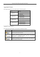
Network Video Recorder Quick Start Guide Applicable Models This manual is applicable to the models listed in the following table. Series DS-7100NI-Q1 DS-7100NI-Q1/P DS-7100NI-Q1/M DS-7100NI-Q1/P/M Model DS-7104NI-Q1 DS-7108NI-Q1 DS-7104NI-Q1/4P DS-7108NI-Q1/8P DS-7104NI-Q1/M DS-7108NI-Q1/M DS-7104NI-Q1/4P/M DS-7108NI-Q1/8P/M Symbol Conventions The symbols that may be found in this document are defined as follows.
Network Video Recorder Quick Start Guide Safety Instructions Proper configuration of all passwords and other security settings is the responsibility of the installer and/or end-user. In the use of the product, you must be in strict compliance with the electrical safety regulations of the nation and region. Please refer to technical specifications for detailed information.
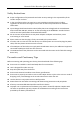
Network Video Recorder Quick Start Guide Power Supply Instructions Use only power supplies listed in the user instructions. NVR Models DS-7104NI-Q1 HWN-2104H DS-7108NI-Q1 HWN-2108H DS-7104NI-Q1/M HWN-2104MH DS-7108NI-Q1/M HWN-2108MH DS-7104NI-Q1/4P HWN-2104H-4P DS-7104NI-Q1/4P/M HWN-2104MH-4P Standard Power Supply Models Manufacturer European MSA-C1500IC12.0-18P-DE ADS-26FSG-12 12018EPG KL-AD3060VA KPD-018-VI MOSO Power Supply Technology Co.,Ltd Shenzhen HONOR Electronic Co.
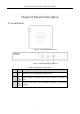
Network Video Recorder Quick Start Guide Chapter1 Panels Description 1.1 Front Panel Figure 1-1 DS-7100NI-Q1 (/P) Series Figure 1-2 DS-7100NI-Q1 (/P)/M Series Table 1-1 Description of Front Panel No. Icon Description 1 Indicator turns red when NVR is powered up. 2 Indicator lights in red when data is being read from or written to HDD. 3 Indicator blinks blue when network connection is functioning properly.
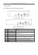
Network Video Recorder Quick Start Guide 1.2 Rear Panel DS-7100NI-Q1 and DS-7100NI-Q1/M Series Figure 1-3 DS-7100NI-Q1 Rear Panel Figure 1-4 DS-7100NI-Q1/M Rear Panel Table 1-2 Description of Rear Panel No. Item Description 1 Power Supply 12 VDC power supply. 2 VGA Interface DB9 connector for VGA output. Display local video output and menu. 3 HDMI Interface HDMI video output connector.
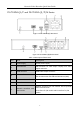
Network Video Recorder Quick Start Guide DS-7100NI-Q1/P and DS-7100NI-Q1/P/M Series Figure 1-5 DS-7100NI-Q1/P Rear Panel Figure 1-6 DS-7100NI-Q1/P/M Rear Panel Table 1-3 Description of Rear Panel No. Item Description 1 Power Supply 12 VDC power supply. VGA Interface DB9 connector for VGA output. Display local video output and menu. HDMI Interface HDMI video output connector. USB Interface Universal Serial Bus (USB) ports for additional devices such as USB mouse and USB Hard Disk Drive (HDD).
Network Video Recorder Quick Start Guide Chapter 2 Installation and Connections 2.1 NVR Installation During installation of the NVR: Use brackets for rack mounting. Ensure ample room for audio and video cables. When routing cables, ensure that the bend radius of the cables are no less than five times than its diameter. Connect the alarm cable. Allow at least 2cm (≈0.75-inch) of space between racks mounted devices. Ensure the NVR is grounded.
Network Video Recorder Quick Start Guide 4) Connect the other end of power cable to the device motherboard. Figure 2-2 Connect Cables Step 3 Set the device up, match HDD screw threads with the reserved holes on the device bottom, and fix HDD with screws. Figure 2-3 Fix HDD to Device Bottom Step 4 (Optional) Repeat the steps above to install other HDDs. Step 5 Reinstall the device cover and fasten screws. 2.
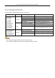
Network Video Recorder Quick Start Guide Bit Rate Storage Used 96K 42M 128K 56M 160K 70M 192K 84M 224K 98M 256K 112M 320K 140M 384K 168M 448K 196M 512K 225M 640K 281M 768K 337M 896K 393M 1024K 450M 1280K 562M 1536K 675M 1792K 787M 2048K 900M 4096K 1.8G 8192K 3.6G 16384K 7.2G Please note that supplied values for storage space used is just for reference. The storage values in the chart are estimated by formulas and may have some deviation from actual value.
Network Video Recorder Quick Start Guide Chapter 3 Menu Operation 3.1 Startup and Shutdown Proper startup and shutdown procedures are crucial to expanding the life of the NVR. To start your NVR: Step 1 Check the power supply is plugged into an electrical outlet. It is HIGHLY recommended that an Uninterruptible Power Supply (UPS) be used in conjunction with the device. The Power button) on the front panel should be red, indicating the device is receiving the power.
Network Video Recorder Quick Start Guide Figure 3-2 Set Admin Password STRONG PASSWORD RECOMMENDED–We highly recommend you create a strong password of your own choosing (Using a minimum of 8 characters, including at least three of the following categories: upper case letters, lower case letters, numbers, and special characters.) in order to increase the security of your product.
Network Video Recorder Quick Start Guide 3.3 Using the Unlock Pattern for Login For the Admin user, you can configure the unlock pattern for device login. After the device is activated, you can enter the following interface to configure the device unlock pattern. Step 1 Use the mouse to draw a pattern among the 9 dots on the screen. Release the mouse when the pattern is done. Figure 3-4 Draw the Pattern Connect at least 4 dots to draw the pattern. Each dot can be connected for once only.
Network Video Recorder Quick Start Guide 3.4 User Login Purpose: If NVR has logged out, you must login the device before operating the menu and other functions. Step 1 Select the User Name in the dropdown list. Figure 3-6 Login Step 2 Input Password. Step 3 Click OK. In the Login dialog box, if you enter the wrong password 7 times, the current user account will be locked for 60 seconds. 3.
Network Video Recorder Quick Start Guide 3.6 Network Settings Purpose: Network settings must be properly configured before you operate NVR over network. Step 1 Enter the general network settings interface. Menu > Configuration > Network > General Figure 3-8 Network Settings Step 2 Configure the following settings: NIC Type, IPv4 Address, IPv4 Gateway, MTU and DNS Server.
Network Video Recorder Quick Start Guide Figure 3-9 Add IP Camera Step 3 Select the detected IP camera and click Add to add it directly, and you can click Search to refresh the online IP camera manually. Or you can choose to custom add the IP camera by editing the parameters in the corresponding text field and then click Add to add it. 3.8 Live View Icons are provided on screen in Live View mode to indicate camera status.
Network Video Recorder Quick Start Guide Purpose: Two kinds of record types are introduced in the following section, including Instant Record and All-day Record. And for other record types, you may refer to the user manual for detailed information. After rebooting all the manual records enabled are canceled. Step 1 On the live view window, right lick the window and move the cursor to the Start Recording option, and select Continuous Record or Motion Detection Record on your demand.
Network Video Recorder Quick Start Guide Figure 3-11 Playback Interface Step 4 Select the channel(s) to or execute simultaneous playback of multiple channels.
Network Video Recorder Quick Start Guide Chapter 4 Accessing by Web Browser You shall acknowledge that the use of the product with Internet access might be under network security risks. For avoidance of any network attacks and information leakage, please strengthen your own protection. If the product does not work properly, please contact with your dealer or the nearest service center. Purpose: You can get access to the device via web browser.
Network Video Recorder Quick Start Guide If the device is already activated, enter the user name and password in the login interface, and click Login. Figure 4-2 Login Step 3 Install the plug-in before viewing the live video and managing the camera. Please follow the installation prompts to install the plug-in. You may have to close the web browser to finish the installation of the plug-in.
Network Video Recorder Quick Start Guide 23 UD09057B