
Quick Start Guide

DVR Quick Start Guide (QSG)
DS-73xxHUI-K4, DS-73xxHQI-K4, DS-90xxHUI-K8
© 2017 Hikvision USA Inc. • All Rights Reserved • Any and all information, including, among others, wordings, pictures, and graphs are the properties of Hangzhou Hikvision Digital
Technology Co., Ltd., or its subsidiaries (hereinafter referred to as “Hikvision”).
This user manual (hereinafter referred to as “Manual”) cannot be reproduced, changed, translated, or distributed, partially or wholly, by any means, without the prior written
permission of Hikvision. Unless otherwise stipulated, Hikvision does nbot make any warranties, guarantees, or representations, express or implied, regarding the Manual.
About this Manual: The Manual includes instructions for using and managing the product. Pictures, charts, images, and all other information hereinafter are for description and
explanation only. The information contained in the Manual is subject to change, without notice, due to firmware updates or other reasons. Please find the latest version on the company
Website (
http://www.hikvision.com/us). Use this Manual under the guidance of professionals.
Trademarks Acknowledgement: and other Hikvision trademarks and logos are the properties of Hikvision in various jurisdictions. Other trademarks and logos
mentioned below are the properties of their respective owners.
Legal Disclaimer: TO THE MAXIMUM EXTENT PERMITTED BY APPLICABLE LAW, THE PRODUCT DESCRIBED, WITH ITS HARDWARE, SOFTWARE, AND FIRMWARE, IS
PROVIDED “AS IS,” WITH ALL FAULTS AND ERRORS, AND HIKVISION MAKES NO WARRANTIES, EXPRESS OR IMPLIED, INCLUDING WITHOUT LIMITATION,
MERCHANTABILITY, SATISFACTORY QUALITY, FITNESS FOR A PARTICULAR PURPOSE, AND NON-INFRINGEMENT OF THIRD PARTY. IN NO EVENT WILL HIKVISION, ITS
DIRECTORS, OFFICERS, EMPLOYEES, OR AGENTS BE LIABLE TO YOU FOR ANY SPECIAL, CONSEQUENTIAL, INCIDENTAL, OR INDIRECT DAMAGES, INCLUDING,
AMONG OTHERS, DAMAGES FOR LOSS OF BUSINESS PROFITS, BUSINESS INTERRUPTION, OR LOSS OF DATA OR DOCUMENTATION, IN CONNECTION WITH THE USE
OF THIS PRODUCT, EVEN IF HIKVISION HAS BEEN ADVISED OF THE POSSIBILITY OF SUCH DAMAGES.
REGARDING TO THE PRODUCT WITH INTERNET ACCESS, THE USE OF PRODUCT SHALL BE WHOLLY AT YOUR OWN RISKS. HIKVISION SHALL NOT TAKE ANY
RESPONSIBILITIES FOR ABNORMAL OPERATION, PRIVACY LEAKAGE, OR OTHER DAMAGES RESULTING FROM CYBER ATTACK, HACKER ATTACK, VIRUS
INSPECTION, OR OTHER INTERNET SECURITY RISKS; HOWEVER, HIKVISION WILL PROVIDE TIMELY TECHNICAL SUPPORT IF REQUIRED.
SURVEILLANCE LAWS VARY BY JURISDICTION. CHECK ALL RELEVANT LAWS IN YOUR JURISDICTION BEFORE USING THIS PRODUCT IN ORDER TO ENSURE THAT
YOUR USE CONFORMS TO THE APPLICABLE LAW. HIKVISION SHALL NOT BE LIABLE IN THE EVENT THAT THIS PRODUCT IS USED FOR ILLEGITIMATE PURPOSES.
IN THE EVENT OF ANY CONFLICTS BETWEEN THIS MANUAL AND THE APPLICABLE LAW, THE LATER PREVAILS.
Regulatory Information
FCC Information
FCC Compliance: This equipment has been tested and found to comply with the limits for a digital device, pursuant to part 15 of the FCC Rules. These limits are designed to
provide reasonable protection against harmful interference when the equipment is operated in a commercial environment. This equipment generates, uses, and can radiate radio
frequency energy and, if not installed and used in accordance with the instruction manual, may cause harmful interference to radio communications. Operation of this equipment in a
residential area is likely to cause harmful interference in which case the user will be required to correct the interference at his own expense.
FCC Conditions: This device complies with part 15 of the FCC Rules. Operation is subject to the following two conditions:
1.
This device may not cause harmful interference.
2.
This device must accept any interference received, including interference that may cause undesired operation.
EU Conformity Statement
This product and, if applicable, the supplied accessories too are marked with “CE” and comply therefore with the applicable harmonized European standards listed
under the EMC Directive 2004/108/EC, the RoHS Directive 2011/65/EU.
2012/19/EU (WEEE Directive): Products marked with this symbol cannot be disposed of as unsorted municipal waste in the European Union. For proper recycling,
return this product to your local supplier upon the purchase of equivalent new equipment, or dispose of it at designated collection points. For more information see:
www.recyclethis.info
2006/66/EC (battery directive): This product contains a battery that cannot be disposed of as unsorted municipal waste in the European Union. See the product
documentation for specific battery information. The battery is marked with this symbol, which may include lettering to indicate cadmium (Cd), lead (Pb), or mercury (Hg).
For proper recycling, return the battery to your supplier or to a designated collection point. For more information
see: www.recyclethis.info.
Industry Canada ICES-003 Compliance: This device meets the CAN ICES-3 (A)/NMB-3(A) standards requirements.
Safety Instruction: These instructions are intended to ensure that the user uses the product correctly to avoid danger or property loss. The precautions are divided into “Warnings”
and “Cautions.”
WARNINGS: Follow these safeguards to prevent serious injury or death; serious injury or death may occur if any of the warnings are neglected.
• Proper configuration of all passwords and other security settings is the responsibility of the installer and/or end-user.
• In the use of the product, you must be in strict compliance with the electrical safety regulations of the nation and region. Refer to technical specifications for detailed information.
• Input voltage should meet both the SELV (Safety Extra Low Voltage) and the Limited Power Source with 24 VAC or 12 VDC according to the IEC60950-1 standard. Refer to
technical specifications for detailed information.
• Do not connect several devices to one power adapter as adapter overload may cause over-heating or a fire hazard.
• Make sure that the plug is firmly connected to the power socket. When the product is mounted on wall or ceiling, the device shall be firmly fixed.
• If smoke, odor, or noise rise from the device, turn off the power at once and unplug the power cable, and then contact the service center.
CAUTIONS: Follow these precautions to prevent potential injury or material damage; injury or equipment damage may occur if any of the cautions are neglected.
• Make sure the power supply voltage is correct before using the device.
• Do not drop the device or subject it to physical shock.
• If cleaning is necessary, use clean cloth with a bit of ethanol and wipe it gently. If the device will not be used for an extended period, protect it from dirt.
• Do not place the device in extremely hot, cold, dusty, or damp locations, and do not expose it to high electromagnetic radiation. Do not operate product in outside of its stated
environmental specs.
• To avoid heat accumulation, good ventilation is required for the operating environment.
• Keep the device away from liquids while in use.
• While in delivery, the device shall be packed in its original packing, or packing of the same durability.
• Regular part replacement: some equipment parts (e.g., electrolytic capacitor) shall be replaced regularly according to their average endurance time. The average time varies
because of differences between operating environments and usage history, so regular checking is recommended for all users. Contact your dealer for more details.
• Improper use or replacement of the battery may result in hazard of explosion. Replace with the same or equivalent type only. Dispose of used batteries according to the
instructions provided by the battery manufacturer.
• If the product does not work properly, contact your dealer or the nearest service center. Never attempt to disassemble the device yourself. (We shall not assume any
responsibility for problems caused by unauthorized repair or maintenance.)
n
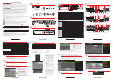
W H A T ’ S I N T H E B O X
Make sure the following items are in your box:
DVR
Mouse
Remote
AAA Cells
(x 2)
Keys
(DS-90xxHUI
)
Power Cord
HDD Screws
(installed)
SATA Cable
(installed)
HDD Power Cable
(installed)
Rack
Ears
(8-, 16-ch = x 2)
HDD Rails
(DS-90xxHUI)
QSG
DVD
n
M E N U T R E E
Use this menu tree to navigate the embedded menus.
n
F R O N T P A N E L S
Figure 1, DS-73xxHUI-K4, DS-73xxHQI-K4 Front Panel
n
F R O N T P A N E L S ( c o n t i n u e d )
Figure 2, DS-90xxHUI-K8 Front Panel
No.
Name
Function Description
1
POWER
Green when DVR is powered up
2
READY
Green, indicating that the DVR is functioning properly
3 STATUS
Green when device is controlled by IR remote/ted when controlled by keyboard/purple
when IR
remote and keyboard is used at the same time
4
ALARM
Red when a sensor alarm is detected
5
HDD
Flickers red when data is being read from or written to HDD
6
Tx/Rx
Flickers green when network connection is functioning properly
7
Power Switch
Power on/off switch
8
USB Interface
Universal Serial Bus ports for additional devices such as mouse and hard disk drive
9
DVD
-
R/W
DVD
-
R/W slot
10
IR Receiver
Receiver for IR remote control
11
DIRECTION
Navigates between
fields/
items in menus/uses
Up/Down buttons to speed up/slow down playing
video files in Playback mode/Left/Right button will select next and previous record file/cycles
through channels in Live View mode/controls movement of PTZ camera in PTZ control mode
ENTER
Confirms selection
in any of the menu modes/checks checkbox/plays or pauses playing video files
in Playback mode/advances video a single frame in single-frame Playback mode/stops and starts
auto switch in Auto
-
switch mode
12
Composite
Keys
SHIFT
Switches between
numeric/letter input (no light) and composite key functions (light red)
1/MENU
Enters numeral “1”/accesses main menu interface
2/ABC/F1
Enters “2ABC”/F1 in list field selects all items/turns on/off PTZ light in PTZ Control mode, use to
zoom out
image/switches between main and spot video output in live view or playback mode
3/DEF/F2
Enters “3DEF”/F2 changes tab pages/zooms in on image in PTZ control mode
4/GHI/ESC
Enters “4GHI”/exits and goes back to previous menu
5/JKL/EDIT
Enters
“5JKL”/deletes characters before cursor/checks checkbox and selects ON/OFF switch/starts
and stops record clipping in playback
6/MNO/PLAY
Enters “6MNO”/accesses playback interface in Playback mode
7/PQRS/REC
Enters “7PQRS”/accesses manual record
interface/manually enables/disables record
8/TUV/PTZ
Enters “8TUV”/accesses PTZ control interface
9/WXYZ/PREV
Enters “9WXYZ”/multi
-
channel display in live view
0/A
Enters “0”/shifts input method in text field (u
pper/
lowercase, alpha, symbols,
numeric).
13 JOG SHUTTLE Control
Moves active selection up and down in menu/cycles through channels in live view mode/jumps 30s
forward or backward in playback mode/controls PTZ camera movement in PTZ control
mode/moves active selection up and down in a m
enu
14
(
Keyed Lock
)
15 Control Keys
ESC/+
Returns to previous menu/press to arm and disarm device in live view mode
REC/Shot
Enters Manual Record settings menu/presses followed by numeral to call PTZ preset in PTZ control
settings/turns audio on and
off in playback mode
PLAY/Auto
Enters playback mode/automatically scans in PTZ control menu
Zoom+
Zooms in the PTZ camera in the PTZ control setting
A/Focus+
Adjusts focus in PTZ Control menu/
changes
input method
(upper/lower case alpha, symbols,
numerals)
Edit/Iris+
Edits text fields and deletes character in front of cursor/checks the checkbox in checkbox
fields/adjusts camera iris in PTZ control mode/generates video clips for backup in playback
mode/enters an
d exits USB device folder and eSATA HDD
Menu/Wiper
Returns to Main menu after successful login
/press and hold five seconds to turn off key beep/starts
wiper (if applicable) in PTZ control mode/shows and hides control interface in playback mode
F1/Light
Selects all items on list when used in list field
F2/Aux
Cycles through tab pages/switches channels in synchronous playback mode
Main Spot/Zoom
-
Switches between main and spot output/zooms out image in PTZ control mode
PREV/Focus-
Switches between single screen and multi
-
screen mode/adjusts focus in conjunction with
A/FOCUS+ button in PTZ control mode
PTZ/Iris
-
Enters PTZ Control mode/adjusts PTZ camera iris in PTZ control mode
n
R E A R P A N E L S
Figure 3, DS-7316HUI-K4 Rear Panel
(Not Shown: DS-7308HUI-K4 with 8 BNC connections, DS-7332HUI-K4 with 32 BNC connections)
Figure 2, DS-7316HQI-K4 Rear Panel
(Not Shown: DS-7308HQI-K4 with 8 BNC connections, DS-7332HQI-K4 with 32 BNC connections)
Figure 3, DS-9016HUI-K8 Rear Panel
(Not Shown: DS-9008HUI-K8 with 8 BNC connections, DS-9032HUI-K8 with 32 BNC connections)
R E A R P A N E L S ( c o n t i n u e d )
Description of DS-73xxHUI-K4, DS-73xxHQI-K4, DS-90xxHUI-K8 Rear Panels
No.
Item
Description
1
VIDEO IN
BNC interface for
TurboHD and analog video input
2
VIDEO OUT
BNC connector for
video output
3
AUDIO IN/LOOP OUT (DS
-
90xxHUI
-
K8
)
RCA connector
4
USB Port
Universal Serial Bus (U
SB) port for additional devices
5
HDMI1/VGA
Simultaneous HDMI1/VGA output. Display local video output and menu.
6
HDMI2
HDMI2 video output connector
(DS
-
73xxHUI
-
K4 and DS
-
90xxHUI
-
K8 only)
7
AUDIO OUT
RCA connector
8
Network Interface
Connector for network
(DS
-
73xxHUI
-
K4 and DS
-
90xxHUI
-
K8 = x2; DS
-
73xxHQI
-
K4 = x1)
9 RS-485 and Alarm Interface
Connector for RS
-
485 devices. T+ and T
-
pins connect to R+ and R
-
pins of PTZ receiver
respectively.
D+, D
-
pin connects to Ta, Tb pin of controller. For cascading
devices, the first DVR’s D+, D
-
pin
should be connected with the D+, D
-
pin of the next DVR.
Connector for alarm input
Connector for alarm output
10
Power Supply
100 to 240 VAC power supply
11
Power Switch
Switch for turning on/off the device
12
GND
Ground
13
LINE IN
BNC connector for audio input
14
eSATA
Connects external SATA HDD, CD/DVD
-
RW
15
RS
-
232 Interface
Connector for RS
-
232 devices
16
ALARM OUT
Connector for alarm output
17
AUDIO IN (for DS
-
9000HUI
-
K8)
RCA connector
1 C O N N E C T D E V I C E S
1. Connect power cord to the DVR.
2. Connect DVR to LAN using Cat 5e cable.
3. Connect video monitor(s) to DVR using HDMI and/or VGA cables, as appropriate.
4. Connect mouse to USB port (wireless mouse can be used in lieu of included mouse).
5. Connect to audio I/O using RCA connectors.
2 S T A R T T H E D V R
1. Plug power plug into 110 to 240 VAC outlet (surge suppressor is recommended).
2. Turn power switch on. Power indicator LED will turn on to indicate unit is starting.
3. After startup, power indicator LED will remain on.
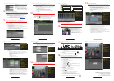
3 L O C A L A C T I V A T I O N
System access requires a secure, user-assigned password.
q
Set Admin Password
First-time access requires user to create an admin
password.
1. Input same password in Create New Password
and Confirm New Password fields.
Strong Password REQUIRED
Password must contain 8 to 16 characters,
combining numbers, lower and upper case
letters, and special characters. At least two
types of the above-mentioned characters are
required. Also, reset password regularly.
2. Click OK to save password and activate device.
3 L O C A L A C T I V A T I O N ( c o n t i n u e d )
Password Strength Levels
STRENGTH
LEVEL
DESCRIPTION
Level 0
(Risky)
DVRs
will
not
accept
password
Password is fewer than eight characters, contains only one character
type
, is same as the user
name, or is mirror writing of the user
name
Level 1
(Weak)
DVRs
will
accept
password
Password contains number + lower case letter or number + upper case letter and is
at
least
eight
characters
Level 2
(Medium/Fair)
DVRs
will
accept
password
Password
contains two types of characters (
neither
number + lower case letter
nor
number +
upper case letter) and is
at least
eight
characters
Level 3
(Strong)
DVRs
will
accept
password
Password contains
three or
more types of characters and is
at
least
eight
characters
The strength level indicator colors can vary by activation process, model number, and device type.
Typical: Risky (no color), Weak (pink), Fair (yellow), Strong (green).
PASSWORD CHARACTERS ALLOWED (ASCII Only):
• Lowercase ASCII Letters • Special Characters
a b c d e f g h I j k l m n o p q r s t u v w x y z . - _ : / @ , ? ! ‘ ( ) $ & “ [ ] { } # % ^ * + = \ | < >
• Uppercase ASCII Letters • Numerals
A B C D E F G H I J K L M N O P Q R S T U V W X Y Z 0 1 2 3 4 5 6 7 8 9
q
Set Unlock
Pattern
Admin user will be prompted to configure an
unlock pattern for login in place of a password.
1. Hold down left mouse button and draw a
pattern by connecting at least four dots on
the screen, each dot connected only once).
2. Release mouse button when done.
3. Draw the same pattern again to confirm it.
NOTE: If you forget the pattern, click “Forgot
Password” to display the normal admin login box.
q
Log In (Unlock Pattern)
1. Draw the unlock pattern to unlock system.
q Log In (Dialog Box)
1. User Name field will be prefilled with
“admin.”
2. Input Password (account will lock to prevent
access for 30 minutes if seven incorrect
password attempts are made).
3. Click OK.
4. After the device is activated, the Attention
box pops up.
q
Export the GUID Password
Recovery File
1. Generate and save GUID (Globally Unique
Identifier) recovery key to be used to reset
password. It is unique to each machine.
1) Insert a USB flash disk into DVR’s USB
port.
2) Click Yes to export GUID recovery key.
Reset Password interface pops up.
3) Navigate to the USB flash disk.
3 L O C A L A C T I V A T I O N ( c o n t i n u e d )
4)
Click
New Folder
to create a folder on the
USB flash disk. Name the folder to identify
the machine (e.g., “Jones Home,
PO3243…”).
5) Double click on the new folder to switch to
that location for saving.
6) Click Export to export the GUID file to the
USB flash disk. System will show the saved
GUID file.
7) Click Back to return to the login screen.
NOTE: The first nine digits after “GUID_” is the serial number of the device from which the GUID was
exported. Digits after the serial number are the date of export.
If multiple GUIDs exist for same unit, always use the file with the latest date.
A GUID can be used only once. Generate and export a new GUID once an issued GUID has been used.
4 I N I T I A L I Z E T H E H A R D D R I V E ( I F N E E D E D )
The system is set up to record upon power up and will beep and display “Do you want to initialize drive”
prompt if the hard drive(s) are not initialized. Click Yes to perform the following steps automatically:
1. Go to MENU > SYSTEM CONFIGURATION > HDD.
2. Use the checkboxes to select the HDDs that need to be initialized.
3. Press INIT.
NOTE: Factory installed HDDs come initialized. Initializing again will erase any record video. This
does not affect settings.)
5 S E T D A T E A N D T I M E
1. Go to MENU > SYSTEM CONFIGURATION > GENERAL.
q
HDD LIST
w TOTAL HDD SPACE
e FREE SPACE
q
w
e
5 S E T D A T E A N D T I M E ( c o n t i n u e d )
6 S E T U P N E T W O R K A C C E S S
A network connection is required to access the cameras remotely.
1. Go to MENU > SYSTEM CONFIGURATION > NETWORK.
2. Enable DHCP (check the checkbox).
3. Press Refresh to update the IPv4 address, subnet mask, and IPv4 default gateway.
4. Disable DHCP (uncheck the checkbox).
5. Change “Preferred DNS Server” value to 8.8.8.8 (leave Alternate DNS Server blank).
7 S E T R E M O T E V I E W I N G P O R T S
After assigning the IP information, click the More Settings tab.
The More Settings tab contains the ports that need to be forwarded for remote access.
q
DATE/TIME
Date and time settings
w TIME ZONE
Time zone and daylight savings
time settings
e ENABLE NTP
Network Time Protocol settings
q
GENERAL TAB
w NIC TYPE (Not changeable)
e ENABLE DHCP
Check box so that router will
assign IP address
r IP V4 ADDRESS
Default 192.0.0.64
t PREFERRED DNS SERVER
Default is 8.8.8.8
y ALTERNATE DNS SERVER
Leave blank
q
w
e
q
w
e
r
t
y