
Manual


User Manual of Network Video Recorder
25
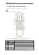
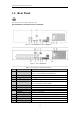
1.4 Rear Panel
The rear panel vaires according to different models.
DS-8600NI-E8, DS-7700NI-E4 and DS-7700NI-E4/P
Figure 1. 8 DS-8600NI-E8 and DS-7700NI-E4
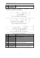
Figure 1. 9 DS-7700NI-E4/P
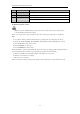
Table 1. 9 Description of Rear Panel Interfaces
No.
Item
Description
1
LAN Interface
1 network interface provided for DS-7700NI-E4/P and 2 network
interfaces for DS-7700NI-E4 and DS-8600NI-E8.
2
AUDIO OUT
RCA connector for audio output.
3
LINE IN
RCA connector for audio input.
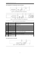
4
HDMI
TM
HDMI
TM
video output connector.
5
USB 3.0 interface
Universal Serial Bus (USB) ports for additional devices such as USB
mouse and USB Hard Disk Drive (HDD).
6
RS-232 Interface
Connector for RS-232 devices.
7
VGA
DB9 connector for VGA output. Display local video output and menu.
8
RS-485 Interface
Half-duplex connector for RS-485 devices.
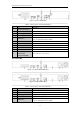
9
ALARM IN
Connector for alarm input.
ALARM OUT
Connector for alarm output.
10
GROUND
Ground (needs to be connected when NVR starts up).
11
AC 100V ~ 240V
AC 100V ~ 240V power supply.
12
Power Switch
Switch for turning on/off the device.
13
Network Interfaces with
Network interfaces for the cameras and to provide power over Ethernet.