Network Video Recorder Quick Start Guide UD.
Network Video Recorder Quick Start Guide TABLE OF CONTENTS Chapter1 Description of Panels ...................................................................................................................... 6 1.1 Front Panel ...................................................................................................................................... 6 1.2 Rear Panel .................................................................................................................................
Network Video Recorder Quick Start Guide Quick Start Guide COPYRIGHT ©2015 Hangzhou Hikvision Digital Technology Co., Ltd. ALL RIGHTS RESERVED. Any and all information, including, among others, wordings, pictures, graphs are the properties of Hangzhou Hikvision Digital Technology Co., Ltd. or its subsidiaries (hereinafter referred to be “Hikvision”).
Network Video Recorder Quick Start Guide Regulatory Information FCC Information FCC compliance: This equipment has been tested and found to comply with the limits for a Class A digital device, pursuant to part 15 of the FCC Rules. These limits are designed to provide reasonable protection against harmful interference when the equipment is operated in a commercial environment.
Network Video Recorder Quick Start Guide Safety Instruction These instructions are intended to ensure that user can use the product correctly to avoid danger or property loss. The precaution measure is divided into “Warnings” and “Cautions” Warnings: Serious injury or death may occur if any of the warnings are neglected. Cautions: Injury or equipment damage may occur if any of the cautions are neglected.
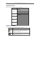
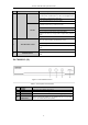
Network Video Recorder Quick Start Guide Applicable Models This manual is applicable to the models listed in the following table.
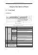
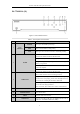
Network Video Recorder Quick Start Guide Chapter1 Description of Panels 1.1 Front Panel DS-9600NI-I8 Figure 1. 1 Front Panel Table 1. 1 Description of Front Panel No. Name Function Description ALARM Turns red when a sensor alarm is detected. READY Turns blue when the device is functioning properly. Turns blue when device is controlled by an IR remote. STATUS Turns red when controlled by a keyboard and purple when IR remote and keyboard is used at the same time.
Network Video Recorder Quick Start Guide No. Name Function Description Turns blue when the corresponding channel is recording; turns red when the channel is in network transmission status; turns pink when the channel is recording and transmitting. 6 USB Interfaces ESC Universal Serial Bus (USB) ports for additional devices such as USB mouse and USB Hard Disk Drive (HDD). Returns to the previous menu. Presses for arming/disarming the device in live view mode. Enters the Manual Record settings menu.
Network Video Recorder Quick Start Guide No. Name Function Description Buttons In the playback mode, use the Up and Down buttons to speed up and slow down recorded video. Use the Left and Right buttons to select the next and previous video files. Cycles through channels in live view mode. Controls the movement of the PTZ camera in PTZ control mode. Confirms selection in any of the menu modes. Checks the checkbox fields. ENTER Plays or pauses the video playing in playback mode.
Network Video Recorder Quick Start Guide DS-7700NI-I4 (/P) Figure 1. 3 DS-7700NI-I4 Series Table 1. 3 Description of Front Panel No. Name Function Description POWER 1 Status Indicators Turns green when NVR is powered up. HDD Blinks red when HDD is reading/writing. Tx/Rx Blinks green when network connection is functioning normally. The Enter button is used to confirm selection in menu mode; or used to check checkbox fields and ON/OFF switch.
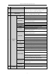
Network Video Recorder Quick Start Guide 1.2 Rear Panel DS-9600NI-I8 Figure 1. 4 Rear Panel Table 1. 4 Description of Interfaces No. Item Description 1 LAN1/LAN2 Interface 2 RJ-45 10/100/1000 Mbps self-adaptive Ethernet interfaces provided. 2 LINE IN RCA connector for audio input. 3 AUDIO OUT 2 RCA connectors for audio output. 4 HDMI1/HDMI2 HDMI video output connector. 5 VGA1/VGA2 DB9 connector for VGA output. Display local video output and menu. 6 USB 3.
Network Video Recorder Quick Start Guide DS-7600NI-I2 and DS-7600NI-I2/P Figure 1. 5 DS-7600NI-I2 Series Figure 1. 6 DS-7600NI-I2/8P Series The DS-7616NI-I2/16P and DS-7632NI-I2/16P provide 16 network Interfaces with PoE function. Table 1. 5 Description of Interfaces No. Item Description 1 Audio In RCA connector for audio input. 2 Audio Out RCA connector for audio output. 3 VGA Interface DB9 connector for VGA output. Display local video output and menu.
Network Video Recorder Quick Start Guide DS-7700NI-I4 and DS-7700NI-I4/P Figure 1. 7 DS-7700NI-I4 Series Figure 1. 8 DS-7700NI-I4/16P Series The DS-7708NI-I4/8P provides 8 network Interfaces with PoE function. Table 1. 6 Description of Rear Panel Interfaces No. Item Description 1 LAN Interface 1 network interface provided for DS-7700NI-I4/P and 2 network interfaces for DS-7700NI-I4. 2 AUDIO OUT RCA connector for audio output. 3 LINE IN RCA connector for audio input.
Network Video Recorder Quick Start Guide Chapter 2 Installation and Connections 2.1 NVR Installation During installation of the NVR: 1. 2. 3. 4. 5. 6. 7. 8. Use brackets for rack mounting. Ensure ample room for audio and video cables. When routing cables, ensure that the bend radius of the cables are no less than five times than its diameter. Connect the alarm cable. Allow at least 2cm (≈0.75-inch) of space between racks mounted devices. Ensure the NVR is grounded.
Network Video Recorder Quick Start Guide Figure 2. 2 Install the HDD 3. Connect one end of the data cable to the NVR motherboard and the other end to the HDD. Figure 2. 3 Connect the data cable 4. Connect the power cable to the HDD. Figure 2. 4 Connect the power cable 5. Re-install the NVR cover and fasten screws.
Network Video Recorder Quick Start Guide 2.3 Connections Wiring of Alarm Input The alarm input is an open/closed relay. To connect the alarm input to the device, use the following diagram. If the alarm input is not an open/close relay, please connect an external relay between the alarm input and the device. Figure 2. 5 Alarm Input Wiring Wiring of Alarm Output To connect to an alarm output (AC or DC load), use the following diagram: Figure 2.
Network Video Recorder Quick Start Guide Using Alarm Connectors To connect alarm devices to the NVR: 1. Disconnect pluggable block from the ALARM IN /ALARM OUT terminal block. 2. Unfasten stop screws from the pluggable block, insert signal cables into slots and fasten stop screws. Ensure signal cables are tight. 3. Connect pluggable block back into terminal block. Controller Connection Figure 2. 7 Controller Connection To connect a controller to the NVR: 1.
Network Video Recorder Quick Start Guide 2.4 HDD Storage Calculation Chart The following chart shows an estimation of storage space used based on recording at one channel for an hour at a fixed bit rate. Bit Rate 96K 128K 160K 192K 224K 256K 320K 384K 448K 512K 640K 768K 896K 1024K 1280K 1536K 1792K 2048K Storage Used 42M 56M 70M 84M 98M 112M 140M 168M 196M 225M 281M 337M 393M 450M 562M 675M 787M 900M 4096K 1.8G 8192K 3.6G 16384K 7.
Network Video Recorder Quick Start Guide Chapter 3 Menu Operation 3.
Network Video Recorder Quick Start Guide To shut down the NVR: 1. Enter the Shutdown menu. Menu > Shutdown Figure 3. 2 Shutdown 2. Select the Shutdown button. 3. Click the Yes button. 3.3 Activating Your Device Purpose: For the first-time access, you need to activate the device by setting an admin password. No operation is allowed before activation. You can also activate the device via Web Browser, SADP or client software. Steps: 1.
Network Video Recorder Quick Start Guide device starts up. You can click YES and follow the wizard to set a strong password. Figure 3. 4 Warning of Weak Password 3.4 Login and Logout User Login Purpose: If NVR has logged out, you must login the device before operating the menu and other functions. Steps: 1. Select the User Name in the dropdown list. Figure 3. 5 Login 2. Input Password. 3. Click OK to log in.
Network Video Recorder Quick Start Guide User Logout Purpose: After logging out, the monitor turns to the live view mode and if you want to perform any operations, you need to enter user name and password log in again. Steps: 1. Enter the Shutdown menu. Menu > Shutdown Figure 3. 7 Logout 2. Click Logout. After you have logged out the system, menu operation on the screen is invalid. It is required to input a user name and password to unlock the system. 3.
Network Video Recorder Quick Start Guide 3.6 Network Settings Purpose: Network settings must be properly configured before you operate NVR over network. Steps: 1. Enter the Network Settings interface. Menu > Configuration > Network Figure 3. 9 Network Settings Two self-adaptive 10M/100M/1000M network interfaces provided for DS-9600NI-I8 and DS-7700NI-I4, and two working modes are configurable: multi-address and network fault tolerance.
Network Video Recorder Quick Start Guide OPTION 1: Steps: 1. Click to select an idle window in the live view mode. 2. Click the icon in the center of the window to pop up the Add IP Camera interface. Figure 3. 10 Add IP Camera 3. Select the detected IP camera and click the Add button to add it directly, and you can click the Search button to refresh the online IP camera manually.
Network Video Recorder Quick Start Guide 3.9 One-Touch RAID Configuration The RAID is supported by DS-9600NI-I8 series NVR only. Purpose: The device supports the RAID storage function. Through one-touch configuration, you can quickly create the disk array. By default, the array type to be created is RAID 5. Before you start: As the default array type is RAID 5, at least 3 HDDs must be installed in you device. And if more than 10 HDDs are installed, 2 arrays can be configured. Steps: 1.
Network Video Recorder Quick Start Guide 4. When the array configuration is completed, click OK button in the pop-up message box to finish the settings. 3.10 Recording Settings Before you start: Make sure that the disk has already been installed. If not, please install a disk and initialize it. You may refer to the user manual for detailed information. Purpose: Two kinds of record types are introduced in the following section, including Instant Record and All-day Record.
Network Video Recorder Quick Start Guide Figure 3. 14 Playback Interface Select the channel (s) you want to play back by checking the checkbox (es), or execute simultaneous playback of multiple channels.
Network Video Recorder Quick Start Guide Chapter 4 Accessing by Web Browser You shall acknowledge that the use of the product with Internet access might be under network security risks. For avoidance of any network attacks and information leakage, please strengthen your own protection. If the product does not work properly, please contact with your dealer or the nearest service center. Purpose: You can get access to the device via web browser.
Network Video Recorder Quick Start Guide Figure 4. 2 Login 3. Install the plug-in before viewing the live video and managing the camera. Please follow the installation prompts to install the plug-in. You may have to close the web browser to finish the installation of the plug-in. After login, you can perform the operation and configuration of the device, including the live view, playback, log search, configuration, etc.
Network Video Recorder Quick Start Guide 29