
User Manual
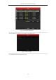
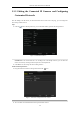
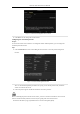
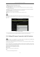
Table Of Contents
- Product Key Features
- Chapter 1 Introduction
- Chapter 2 Getting Started
- Chapter 3 Live View
- Chapter 4 PTZ Controls
- Chapter 5 Recording Settings
- 5.1 Configuring Parameters
- 5.2 Configuring Recording Schedule
- 5.3 Configuring Motion Detection Recording
- 5.4 Configuring Alarm Triggered Recording
- 5.5 Configuring VCA Event Recording
- 5.6 Manual Recording
- 5.7 Configuring Holiday Recording
- 5.8 Configuring Redundant Recording
- 5.9 Configuring HDD Group for Recording
- 5.10 Files Protection
- Chapter 6 Playback
- 6.1 Playing Back Record Files
- 6.2 Auxiliary Functions of Playback
- Chapter 7 Backup
- Chapter 8 Alarm Settings
- Chapter 9 VCA Alarm
- 9.1 Face Detection
- 9.2 Vehicle Detection
- 9.3 Line Crossing Detection
- 9.4 Intrusion Detection
- 9.5 Region Entrance Detection
- 9.6 Region Exiting Detection
- 9.7 Unattended Baggage Detection
- 9.8 Object Removal Detection
- 9.9 Audio Exception Detection
- 9.10 Sudden Scene Change Detection
- 9.11 Defocus Detection
- 9.12 PIR Alarm
- Chapter 10 VCA Search
- Chapter 11 Network Settings
- Chapter 12 HDD Management
- Chapter 13 Camera Settings
- Chapter 14 NVR Management and Maintenance
- Chapter 15 Others
- Chapter 16 Appendix

Network Video Recorder User Manual
48
Example: rtsp://192.168.1.55:554/ch1/main/av_stream.
Protocol Name: Edit the name for the custom protocol.
Enable Substream: If the network camera does not support sub-stream or the sub-stream is not needed
leave the checkbox empty.
Type: The network camera adopting custom protocol must support getting stream through standard RTSP.
Transfer Protocol: Select the transfer protocol for the custom protocol.
Port: Set the port No. for the custom protocol.
Path: Set the resource path for the custom protocol. E.g., ch1/main/av_stream.
The protocol type and the transfer protocols must be supported by the connected network camera.
After adding the customized protocols, you can see the protocol name is listed in the dropdown list, please refer to
Figure 2. 38.
Figure 2. 38 Protocol Setting
3. Choose the protocols you just added to validate the connection of the network camera.
2.3.4 Editing IP Cameras Connected to the PoE Interfaces
This chapter is only applicable for the following models: DS-7604NI-E1/4P, DS-7600NI-E2/8P,
DS-7600NI-E2/16P, DS-7700NI-E4/8P, DS-7700NI-E4/16P series NVR.
The PoE interfaces enables the NVR system to pass electrical power safely, along with data, on Ethernet cabling to
the connected network cameras.
Up to 4 network cameras can be connected to /4P models, 8 network cameras to /8P models, and 16 network
cameras to /16P models. If you disable the PoE interface, you can also connect to the online network cameras. And
the PoE interface supports the Plug-and-Play function.
To add Cameras for NVR supporting PoE function:
Before you start:
Connect the network cameras via the PoE interfaces.
Steps:
1. Enter the Camera Management interface.