Network Video Recorder Quick Start Guide
Network Video Recorder Quick Start Guide TABLE OF CONTENTS Chapter1 Panels Description .......................................................................................................................... 8 1.1 Front Panel........................................................................................................................................... 8 1.1.1 DS-9600NI Series .....................................................................................................................
Network Video Recorder Quick Start Guide Quick Start Guide COPYRIGHT © 2018 Hangzhou Hikvision Digital Technology Co., Ltd. ALL RIGHTS RESERVED. Any and all information, including, among others, wordings, pictures, graphs are the properties of Hangzhou Hikvision Digital Technology Co., Ltd. or its subsidiaries (hereinafter referred to be “Hikvision”).
Network Video Recorder Quick Start Guide Regulatory Information FCC Information Please take attention that changes or modification not expressly approved by the party responsible for compliance could void the user’s authority to operate the equipment. FCC compliance: This equipment has been tested and found to comply with the limits for a Class A digital device, pursuant to part 15 of the FCC Rules.
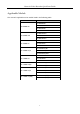
Network Video Recorder Quick Start Guide Applicable Models This manual is applicable to the models listed in the following table.
Network Video Recorder Quick Start Guide Symbol Conventions The symbols that may be found in this document are defined as follows. Symbol Description Provides additional information to emphasize or supplement important points of the main text. Indicates a potentially hazardous situation, which if not avoided, could result in equipment damage, data loss, performance degradation, or unexpected results.
Network Video Recorder Quick Start Guide Safety Instructions Proper configuration of all passwords and other security settings is the responsibility of the installer and/or end-user. In the use of the product, you must be in strict compliance with the electrical safety regulations of the nation and region. Please refer to technical specifications for detailed information.
Network Video Recorder Quick Start Guide When installing the device into a cabinet over 2U height, it is suggest to use rack shelf to bear the weight. If the cabinet height is over 4U, it is suggest to use slide rails or rack shelf to bear the weight.
Network Video Recorder Quick Start Guide Chapter1 Panels Description 1.1 Front Panel 1.1.
Network Video Recorder Quick Start Guide Table 1-1 Panel Description No. Name Function Description ALARM Turns red when a sensor alarm is detected. READY Turns blue when the device is functioning properly. Turns blue when device is controlled by an IR remote. STATUS 1 Status Indicators Turns red when controlled by a keyboard and purple when IR remote and keyboard is used at the same time. HDD Flickers red when data is being read from or written to HDD. MODEM Reserved for future usage.
Network Video Recorder Quick Start Guide No. Name Function Description 6 Universal Serial Bus (USB) ports for additional devices such as USB mouse and USB Hard Disk Drive (HDD). USB Interfaces Returns to the previous menu. ESC Presses for arming/disarming the device in live view mode. Enters the Manual Record settings menu. REC/SHOT Presses this button followed by a numeric button to call a PTZ preset in PTZ control settings. Turns audio on/off in the playback mode.
Network Video Recorder Quick Start Guide No. Name Function Description Turns on/off PTZ light (if applicable) in PTZ control mode. Switches between play and reverse play in playback mode. Cycles through tab pages. F2/ AUX Switches between channels in synchronous playback mode. Returns to the Main menu (after successful login). MENU/WIPER Presses and holds the button for five seconds to turn off audible key beep. Starts wiper (if applicable) in PTZ control mode.
Network Video Recorder Quick Start Guide No. Name Function Description Plays or pauses the video playing in playback mode. Advances the video by a single frame in single-frame playback mode. Stops/starts auto switch in auto-switch mode. Moves the active selection up and down in a menu. 9 JOG SHUTTLE Control Cycles through different channels in live view mode. Jumps 30s forward/backward in video files in the playback mode. Controls the movement of the PTZ camera in PTZ control mode.
Network Video Recorder Quick Start Guide Table 1-2 Panel Description No. Name Function Description POWER 1 Status HDD Indicators Tx/Rx Turns green when NVR is powered up. Blinks red when HDD is reading/writing. Blinks green when network connection is functioning normally. The Enter button is used to confirm selection in menu mode; or used to check checkbox fields and ON/OFF switch. In playback mode, it can be used to play or pause the video.
Network Video Recorder Quick Start Guide 1.1.3 DS-7600NI Series Figure 1-4 DS-7600NI Series Table 1-3 Panel Description No. Name Connections 1 POWER Turns green when NVR is powered up. 2 HDD Flickers red when data is being read from or written to HDD. 3 Tx/Rx Flickers blue when network connection is functioning properly. 4 USB Interface Universal Serial Bus (USB) port for additional devices such as USB mouse and USB Hard Disk Drive (HDD). 1.2 Rear Panel 1.2.
Network Video Recorder Quick Start Guide Figure 1-6 DS-9600NI-I16 Series Table 1-4 Panel Description No. Name Description 1 LAN1/LAN2 Interface 2 RJ-45 10/100/1000 Mbps self-adaptive Ethernet interfaces provided. 2 LINE IN RCA connector for audio input. 3 AUDIO OUT 2 RCA connectors for audio output. 4 HDMI1/HDMI2 HDMI video output connector. 5 VGA1/VGA2 DB9 connector for VGA output. Display local video output and menu. 6 USB 3.
Network Video Recorder Quick Start Guide 1.2.2 DS-7700NI Series Figure 1-7 DS-7700NI-I4 and DS-7700NI-K4 Series Figure 1-8 DS-7700NI-I4(B) and DS-7700NI-K4(B) Series Figure 1-9 DS-7700NI-I4/16P and DS-7700NI-K4/16P Series Figure 1-10 DS-7700NI-I4/16P(B) and DS-7700NI-K4/16P(B) Series The DS-7708NI-I4/8P and DS-7708NI-K4/8P provides 8 network Interfaces with PoE function. Table 1-5 Panel Description No.
Network Video Recorder Quick Start Guide 2 AUDIO OUT RCA connector for audio output. 3 LINE IN RCA connector for audio input. 4 HDMI HDMI video output connector. 5 USB 3.0 interface Universal Serial Bus (USB) ports for additional devices such as USB mouse and USB Hard Disk Drive (HDD). 6 RS-232 Interface Connector for RS-232 devices. 7 VGA DB9 connector for VGA output. Display local video output and menu. 8 RS-485 Interface Half-duplex connector for RS-485 devices.
Network Video Recorder Quick Start Guide Figure 1-12 DS-7600NI-I2/8P Series The DS-7616NI-I2/16P and DS-7632NI-I2/16P provide 16 network Interfaces with PoE function. Panel Description Table 1-6 Panel Description No. Name Description 1 Audio In RCA connector for audio input. 2 Audio Out RCA connector for audio output. 3 VGA Interface DB9 connector for VGA output. Display local video output and menu. 4 HDMI Interface HDMI video output connector. 5 ALARM IN Connector for alarm input.
Network Video Recorder Quick Start Guide Chapter 2 Installation and Connections 2.1 Installation During installation of the NVR: Use brackets for rack mounting. Ensure ample room for audio and video cables. When routing cables, ensure that the bend radius of the cables are no less than five times than its diameter. Connect the alarm cable. Allow at least 2cm (≈0.75-inch) of space between racks mounted devices. Ensure the NVR is grounded.
Network Video Recorder Quick Start Guide Step 2 Unlock the front panel with the attached key, and press the buttons on both sides of the front panel to open it. Figure 2-2 Open Front Panel Step 3 Insert the HDD until it is fixed firmly. Figure 2-3 Insert HDD Step 4 (Optional) Repeat the steps above to install other HDDs. Step 5 Close the front panel and lock it with key. 2.2.
Network Video Recorder Quick Start Guide 1) 2) 3) 4) Connect one end of data cable to the device motherboard. Connect the other end of data cable to HDD. Connect one end of power cable to HDD. Connect the other end of power cable to the device motherboard. Figure 2-5 Connect Cables Step 3 Set the device up, match HDD screw threads with the reserved holes on the device bottom, and fix HDD with screws. Figure 2-6 Fix HDD to Device Bottom Step 4 (Optional) Repeat the steps above to install other HDDs.
Network Video Recorder Quick Start Guide Figure 2-7 Alarm Input Wiring 2.3.2 Alarm Output Wiring To connect to an alarm output (AC or DC load), use the following diagram: Figure 2-8 Alarm Output Wiring For a DC load, the jumpers can be used within the limit of 12V/1A safely. To connect an AC load, jumpers should be left open (you must remove the jumper on the motherboard in the NVR). Use an external relay for safety (as shown in the figure above).
Network Video Recorder Quick Start Guide 2.3.4 Controller Connection Figure 2-9 Controller Connection To connect a controller to the NVR: Step 2 Disconnect pluggable block from the KB terminal block. Step 3 Unfasten stop screws from the KB D+, D- pluggable block, insert signal cables into slots and fasten stop screws. Ensure signal cables are in tight. Step 4 Connect Ta on controller to D+ on terminal block and Tb on controller to D- on terminal block. Fasten stop screws.
Network Video Recorder Quick Start Guide 2.4 HDD Storage Calculation Chart The following chart shows an estimation of storage space used based on recording at one channel for an hour at a fixed bit rate. Bit Rate Storage Used 96K 42M 128K 56M 160K 70M 192K 84M 224K 98M 256K 112M 320K 140M 384K 168M 448K 196M 512K 225M 640K 281M 768K 337M 896K 393M 1024K 450M 1280K 562M 1536K 675M 1792K 787M 2048K 900M 4096K 1.8G 8192K 3.6G 16384K 7.
Network Video Recorder Quick Start Guide Chapter 3 Menu Operation 3.1 Start up Your Device Proper startup and shutdown procedures are crucial to expanding the life of the NVR. To start your device: Step 1 Check the power supply is plugged into an electrical outlet. It is HIGHLY recommended that an Uninterruptible Power Supply (UPS) be used in conjunction with the device. The Power button on the front panel should be red, indicating the device is receiving the power.
Network Video Recorder Quick Start Guide We highly recommend you create a strong password of your own choosing (using a minimum of 8 characters, including at least three of the following categories: upper case letters, lower case letters, numbers, and special characters.) in order to increase the security of your product. We also recommend that you reset your password regularly. Especially in the high security systems, resetting the password monthly or weekly can better protect your product.
Network Video Recorder Quick Start Guide Connect at least 4 dots to draw the pattern. Each dot can be connected for once only. Step 3 Draw the same pattern again to confirm it. When the two patterns match, the pattern is configured successfully. If the two patterns are different, you must set the pattern again. 3.4 Log in to the System If the device has logged out, you must log in the device before operating the menu and other functions.
Network Video Recorder Quick Start Guide Check the checkbox to enable Setup Wizard when device starts. Click Next to continue the setup wizard. Follow the guide of the Setup Wizard to configure the system resolution, system date/time, network settings, HDD management, record settings, etc. Figure 3-4 Wizard 3.6 Network Settings Network settings must be properly configured before you operate the device over a network. Step 1 Go to System > Network > TCP/IP.
Network Video Recorder Quick Start Guide Step 3 In the General Settings interface, you can configure the following settings: NIC Type, IPv4 Address, IPv4 Gateway, MTU, and DNS Server. Step 4 If the DHCP server is available, you can check DHCP to automatically obtain an IP address and other network settings from that server. Step 5 After having configured the general settings, click the Apply button to save the settings. 3.
Network Video Recorder Quick Start Guide The function is only available when you use HIKVISION protocol. Step 6 (Optional) Check Verify Certificate to verify the camera with certificate. The certificate is a form of identification for the camera that provides more secure camera authentication. It requires to import the IP camera certificate to the NVR first when you use this function. 1) Log in the IP camera by web browser.
Network Video Recorder Quick Start Guide Install at least 3 HDDs. If more than 10 HDDs are installed, 2 arrays will be created. To maintain reliable and stable running of the HDDs, it is recommended to use enterprise-level HDDs with the same model and capacity. Step 1 Go to Storage > RAID Setup > Physical Disk. Figure 3-7 Physical Disk Step 2 Click One-touch Config. Step 3 Edit the array name in Array Name text filed and click OK to start configuring.
Network Video Recorder Quick Start Guide Step 4 Select a Record Type. The record type can be Continuous, Motion Detection, Alarm, Motion | Alarm, Motion & Alarm, Event, etc. Figure 3-8 Record Schedule Step 5 Select a day and click-and-drag the mouse on the time bar to set the record schedule. Step 6 Click Apply to save the settings. 3.
Network Video Recorder Quick Start Guide Figure 3-9 Playback Interface 33
Network Video Recorder Quick Start Guide Chapter 4 Access by Web Browser You shall acknowledge that the use of the product with Internet access might be under network security risks. For avoidance of any network attacks and information leakage, strengthen your own protection. If the product does not work properly, please contact with your dealer or the nearest service center. Purpose: You can get access to the device via Web browser. You may use one of the following Web browsers: Internet Explorer 6.
Network Video Recorder Quick Start Guide If the device is already activated, enter the user name and password in the login interface, and click the Login button. Figure 4-2 Login Step 3 Install the plug-in before viewing the live video and managing the camera. Follow the installation prompts to install the plug-in. You may have to close the Web browser to finish plug-in installation.
Network Video Recorder Quick Start Guide 36 UD11427B