
Quick Start Guide
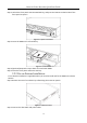
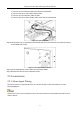
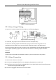
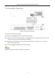
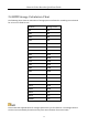

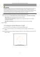
Table Of Contents

Network Video Recorder Quick Start Guide
22
Figure 2-7 Alarm Input Wiring
2.3.2 Alarm Output Wiring
To connect to an alarm output (AC or DC load), use the following diagram:
Figure 2-8 Alarm Output Wiring
For a DC load, the jumpers can be used within the limit of 12V/1A safely.
To connect an AC load, jumpers should be left open (you must remove the jumper on the
motherboard in the NVR). Use an external relay for safety (as shown in the figure above).
There are 4 jumpers (JP6, JP9, JP10, and JP11) on the motherboard, each corresponding with one
alarm output. By default, jumpers are connected. To connect an AC load, jumpers should be
removed.
EXAMPLE:
If you connect an AC load to the NVR alarm output 3, you must remove the JP 3 jumper.
2.3.3 Alarm Connection
To connect alarm devices to the NVR:
Step 1 Disconnect pluggable block from the ALARM IN /ALARM OUT terminal block.
Step 2 Unfasten stop screws from the pluggable block, insert signal cables into slots and fasten stop
screws. Ensure signal cables are tight.
Step 3 Connect pluggable block back into terminal block.