
Quick Start Guide
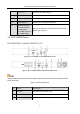
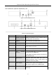
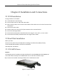
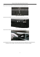
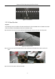
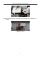
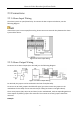
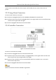
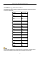
Table Of Contents
- Chapter1 Panels Description
- Chapter 2 Installation and Connections
- Chapter 3 Menu Operation
- Chapter 4 Accessing by Web Browser

Network Video Recorder Quick Start Guide
27
2.3 Connections
2.3.1 Alarm Input Wiring
The alarm input is an open/closed relay. To connect the alarm input to the device, use the
following diagram.
If the alarm input is not an open/close relay, please connect an external relay between the alarm
input and the device.
Figure 2-10 Alarm Input Wiring
2.3.2 Alarm Output Wiring
To connect to an alarm output (AC or DC load), use the following diagram:
Figure 2-11 Alarm Output Wiring
For DC load, the jumpers can be used within the limit of 12V/1A safely.
To connect an AC load, jumpers should be left open (you must remove the jumper on the
motherboard in the NVR). Use an external relay for safety (as shown in the figure above).
There are 4 jumpers (JP6, JP9, JP10, and JP11) on the motherboard, each corresponding with one
alarm output. By default, jumpers are connected. To connect an AC load, jumpers should be
removed.
Example: