Network Video Recorder Quick Start Guide UD02353B
Network Video Recorder Quick Start Guide TABLE OF CONTENTS Chapter1 Panels Description .......................................................................................................................... 7 1.1 Front Panel........................................................................................................................................... 7 1.1.1 DS-9600NI Series .....................................................................................................................
Network Video Recorder Quick Start Guide Quick Start Guide COPYRIGHT © 2016 Hangzhou Hikvision Digital Technology Co., Ltd. ALL RIGHTS RESERVED. Any and all information, including, among others, wordings, pictures, graphs are the properties of Hangzhou Hikvision Digital Technology Co., Ltd. or its subsidiaries (hereinafter referred to be “Hikvision”).
Network Video Recorder Quick Start Guide Regulatory Information FCC Information Please take attention that changes or modification not expressly approved by the party responsible for compliance could void the user’s authority to operate the equipment. FCC compliance: This equipment has been tested and found to comply with the limits for a Class A digital device, pursuant to part 15 of the FCC Rules.
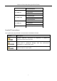
Network Video Recorder Quick Start Guide Applicable Models This manual is applicable to the models listed in the following table.
Network Video Recorder Quick Start Guide DS-7732NI-K4/16P DS-7608NI-K2 DS-7600NI-K2 DS-7616NI-K2 DS-7632NI-K2 DS-7608NI-K2/8P DS-7600NI-K2/P DS-7616NI-K2/16P DS-7632NI-K2/16P DS-7604NI-K1 DS-7600NI-K1 DS-7608NI-K1 DS-7616NI-K1 DS-7600NI-K1/4P DS-7604NI-K1/4P Symbol Conventions The symbols that may be found in this document are defined as follows. Symbol Description Provides additional information to emphasize or supplement important points of the main text.
Network Video Recorder Quick Start Guide Safety Instructions Proper configuration of all passwords and other security settings is the responsibility of the installer and/or end-user. In the use of the product, you must be in strict compliance with the electrical safety regulations of the nation and region. Please refer to technical specifications for detailed information.
Network Video Recorder Quick Start Guide Chapter1 Panels Description 1.1 Front Panel 1.1.
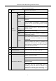
Network Video Recorder Quick Start Guide Table 1-1 Panel Description No. Name Function Description ALARM Turns red when a sensor alarm is detected. READY Turns blue when the device is functioning properly. Turns blue when device is controlled by an IR remote. STATUS 1 Status Indicators Turns red when controlled by a keyboard and purple when IR remote and keyboard is used at the same time. HDD Flickers red when data is being read from or written to HDD. MODEM Reserved for future usage.
Network Video Recorder Quick Start Guide No. Name Function Description 6 Universal Serial Bus (USB) ports for additional devices such as USB mouse and USB Hard Disk Drive (HDD). USB Interfaces Returns to the previous menu. ESC Presses for arming/disarming the device in live view mode. Enters the Manual Record settings menu. REC/SHOT Presses this button followed by a numeric button to call a PTZ preset in PTZ control settings. Turns audio on/off in the playback mode.
Network Video Recorder Quick Start Guide No. Name Function Description Turns on/off PTZ light (if applicable) in PTZ control mode. Switches between play and reverse play in playback mode. Cycles through tab pages. F2/ AUX Switches between channels in synchronous playback mode. Returns to the Main menu (after successful login). MENU/WIPER Presses and holds the button for five seconds to turn off audible key beep. Starts wiper (if applicable) in PTZ control mode.
Network Video Recorder Quick Start Guide No. Name Function Description Plays or pauses the video playing in playback mode. Advances the video by a single frame in single-frame playback mode. Stops/starts auto switch in auto-switch mode. Moves the active selection up and down in a menu. 9 JOG SHUTTLE Control Cycles through different channels in live view mode. Jumps 30s forward/backward in video files in the playback mode. Controls the movement of the PTZ camera in PTZ control mode.
Network Video Recorder Quick Start Guide Table 1-2 Description of Control Panel Buttons No. Name Function Description ALARM Turns red when a sensor alarm is detected. READY Turs blue when the device is functioning properly. Turns blue when device is controlled by an IR remote. STATUS 1 Status Indicators Turns red when controlled by a keyboard and purple when IR remote and keyboard is used at the same time. HDD Flickers red when data is being read from or written to HDD.
Network Video Recorder Quick Start Guide No. Name Function Description Drive (HDD). Returns to the previous menu. ESC Presses for arming/disarming the device in live view mode. Enters the Manual Record settings menu. REC/SHOT Presses this button followed by a numeric button to call a PTZ preset in PTZ control settings. Turns audio on/off in the playback mode. PLAY/AUTO ZOOM+ Enters the playback mode. Automatically scans in the PTZ control menu. Zooms in the PTZ camera in the PTZ control setting.
Network Video Recorder Quick Start Guide No. Name Function Description playback mode. Cycles through tab pages. F2/ AUX Switches between channels in synchronous playback mode. Returns to the Main menu (after successful login). MENU/WIPER Presses and holds the button for five seconds to turn off audible key beep. Starts wiper (if applicable) in PTZ control mode. Shows/hides the control interface in playback mode. PREV/FOCUS- Switches between single screen and multi-screen mode.
Network Video Recorder Quick Start Guide No. Name Function Description Stops/starts auto switch in auto-switch mode. Moves the active selection up and down in a menu. 8 JOG SHUTTLE Control Cycles through different channels in live view mode. Jumps 30s forward/backward in video files in the playback mode. Controls the movement of the PTZ camera in PTZ control mode. 9 POWER ON/OFF Power on/off switch. 1.1.
Network Video Recorder Quick Start Guide Table 1-3 Panel Description No. Name Function Description POWER 1 Status HDD Indicators Tx/Rx Turns green when NVR is powered up. Blinks red when HDD is reading/writing. Blinks green when network connection is functioning normally. The Enter button is used to confirm selection in menu mode; or used to check checkbox fields and ON/OFF switch. In playback mode, it can be used to play or pause the video.
Network Video Recorder Quick Start Guide 1.1.3 DS-7600NI Series Figure 1-6 DS-7600NI Series Table 1-4 Panel Description No. Name Connections 1 POWER Turns green when NVR is powered up. 2 HDD Flickers red when data is being read from or written to HDD. 3 Tx/Rx Flickers blue when network connection is functioning properly. 4 USB Interface Universal Serial Bus (USB) port for additional devices such as USB mouse and USB Hard Disk Drive (HDD). 1.2 Rear Panel 1.2.
Network Video Recorder Quick Start Guide Figure 1-8 DS-9600NI-I16 Series Table 1-5 Panel Description No. Name Description 1 LAN1/LAN2 Interface 2 RJ-45 10/100/1000 Mbps self-adaptive Ethernet interfaces provided. 2 LINE IN RCA connector for audio input. 3 AUDIO OUT 2 RCA connectors for audio output. 4 HDMI1/HDMI2 HDMI video output connector. 5 VGA1/VGA2 DB9 connector for VGA output. Display local video output and menu. 6 USB 3.
Network Video Recorder Quick Start Guide 1.2.2 DS-7700NI Series Figure 1-9 DS-7700NI-I4 and DS-7700NI-K4 Series Figure 1-10 DS-7700NI-I4/16P and DS-7700NI-K4/16P Series The DS-7708NI-I4/8P and DS-7708NI-K4/8P provides 8 network Interfaces with PoE function. Table 1-6 Panel Description No. Name Description 1 LAN Interface 1 network interface provided for DS-7700NI-I4/P and DS-7700NI-K4/P, and 2 network interfaces for DS-7700NI-I4 and DS-7700NI-K4. 2 AUDIO OUT RCA connector for audio output.
Network Video Recorder Quick Start Guide ALARM OUT Connector for alarm output. 10 GROUND Ground (needs to be connected when NVR starts up). 11 AC 100V ~ 240V 100V to 240VAC power supply. 12 Power Switch Switch for turning on/off the device. 13 Network Interfaces with PoE function (supported by DS-7700NI-I4/P and DS-7700NI-K4/P) Network interfaces for the cameras and to provide power over Ethernet. 1.2.
Network Video Recorder Quick Start Guide output and menu. 4 HDMI Interface HDMI video output connector. 5 ALARM IN Connector for alarm input. ALARM OUT Connector for alarm output. 6 LAN Interface Network 1 10/100/1000 interface 7 USB Interface Universal Serial Bus (USB 3.0) ports for additional devices such as USB mouse and USB Hard Disk Drive (HDD). 8 Ground Ground (needs to be connected when NVR starts up).
Network Video Recorder Quick Start Guide DS-7600NI-K1 and DS-7600NI-K1/4P Figure 1-14 DS-7600NI-K1 Series Figure 1-15 DS-7604NI-K1/4P Series Table 1-7 Panel Description Table 1-8 No. Table 1-9 Name Table 1-10 Description 1 Network Interfaces Network interfaces for the cameras and to with PoE function provide power over Ethernet. 2 Audio In RCA connector for audio input. 3 Audio Out RCA connector for audio output. 4 VGA Interface DB9 connector for VGA output.
Network Video Recorder Quick Start Guide Chapter 2 Installation and Connections 2.1 NVR Installation During installation of the NVR: Use brackets for rack mounting. Ensure ample room for audio and video cables. When routing cables, ensure that the bend radius of the cables are no less than five times than its diameter. Connect the alarm cable. Allow at least 2cm (≈0.75-inch) of space between racks mounted devices. Ensure the NVR is grounded.
Network Video Recorder Quick Start Guide Step 2 Insert the key and turn in clockwise direction to open the panel lock. Figure 2-2 Insert Panel Key Step 3 Press the buttons on the panel of two sides and open the front panel. Figure 2-3 Open Panel Lock Step 4 Insert the hard disk along the slot until it is placed into position. Figure 2-4 Insert Hard Disk Step 5 Repeat the above steps to install other hard disks onto the NVR.
Network Video Recorder Quick Start Guide Figure 2-5 Lock Panel 2.2.2 Other Models Purpose: The following section introduces the HDD installation for the DS-7600NI and DS-7700NI series NVR. Take the example of DS-7600NI to describe installation steps. Step 1 Remove the cover from the NVR by unfastening the screws on the rear and side panel. Figure 2-6 Remove Cover Step 2 Connect one end of the data cable to the motherboard of NVR and the other end to the HDD.
Network Video Recorder Quick Start Guide Figure 2-8 Connect Power Cable Step 4 Place the HDD on the bottom of the device and then fasten the screws on the bottom to fix the HDD.
Network Video Recorder Quick Start Guide 2.3 Connections 2.3.1 Alarm Input Wiring The alarm input is an open/closed relay. To connect the alarm input to the device, use the following diagram. If the alarm input is not an open/close relay, please connect an external relay between the alarm input and the device. Figure 2-10 Alarm Input Wiring 2.3.
Network Video Recorder Quick Start Guide If you connect an AC load to the alarm output 3 of the NVR, then you must remove the JP 3 jumper. 2.3.3 Using Alarm Connectors To connect alarm devices to the NVR: Step 1 Disconnect pluggable block from the ALARM IN /ALARM OUT terminal block. Step 2 Unfasten stop screws from the pluggable block, insert signal cables into slots and fasten stop screws. Ensure signal cables are tight. Step 3 Connect pluggable block back into terminal block. 2.3.
Network Video Recorder Quick Start Guide 2.4 HDD Storage Calculation Chart The following chart shows an estimation of storage space used based on recording at one channel for an hour at a fixed bit rate. Bit Rate Storage Used 96K 42M 128K 56M 160K 70M 192K 84M 224K 98M 256K 112M 320K 140M 384K 168M 448K 196M 512K 225M 640K 281M 768K 337M 896K 393M 1024K 450M 1280K 562M 1536K 675M 1792K 787M 2048K 900M 4096K 1.8G 8192K 3.6G 16384K 7.
Network Video Recorder Quick Start Guide Chapter 3 Menu Operation 3.
Network Video Recorder Quick Start Guide Step 2 Press the POWER button on the front panel. The Power LED should turn blue. The unit will begin to start. After the device starts up, the wizard will guide you through the initial settings, including modifying password, date and time settings, network settings, HDD initializing, and recording. To shut down the NVR: Step 3 Enter the Shutdown menu. Menu > Shutdown Figure 3-2 Shutdown Step 4 Select the Shutdown button. Step 5 Click the Yes button. 3.
Network Video Recorder Quick Start Guide STRONG PASSWORD RECOMMENDED–We highly recommend you create a strong password of your own choosing (Using a minimum of 8 characters, including at least three of the following categories: upper case letters, lower case letters, numbers, and special characters.) in order to increase the security of your product.
Network Video Recorder Quick Start Guide Connect at least 4 dots to draw the pattern. Each dot can be connected for once only. Step 2 Draw the same pattern again to confirm it. When the two patterns match, the pattern is configured successfully. Step 3 You can use the configured unlock pattern for future login. Figure 3-6 Draw the Unlock Pattern 3.5 Login and Logout 3.5.1 User Login Purpose: If NVR has logged out, you must login the device before operating the menu and other functions.
Network Video Recorder Quick Start Guide In the Login dialog box, if you enter the wrong password 7 times, the current user account will be locked for 60 seconds. 3.5.2 User Logout Purpose: After logging out, the monitor turns to the live view mode and if you want to perform any operations, you need to enter user name and password log in again. Step 1 Enter the Shutdown menu. Menu > Shutdown Figure 3-8 Logout Step 2 Click Logout.
Network Video Recorder Quick Start Guide Figure 3-9 Wizard 3.7 Network Settings Purpose: Network settings must be properly configured before you operate NVR over network. Step 1 Enter the Network Settings interface.
Network Video Recorder Quick Start Guide Two self-adaptive 10M/100M/1000M network interfaces for DS-9600NI-I8, DS-9600NI-I16, DS-8600NI-K8, DS-7700NI-I4 and DS-7700NI-K4, and the multi-address and network fault tolerance working modes are configurable. One self-adaptive 10M/100M/1000M network interface for DS-7600NI-K2/I2(/P), DS-7700NI-I4/P and DS-7700NI-K4/P. One self-adaptive 10M/100M network interface for DS-7600NI-K1 (/P). Step 2 Select the General tab.
Network Video Recorder Quick Start Guide Figure 3-11 Add IP Camera Step 3 Select the detected IP camera and click the Add button to add it directly, and you can click the Search button to refresh the online IP camera manually. Or you can choose to custom add the IP camera by editing the parameters in the corresponding text field and then click the Add button to add it. 3.9 Live View Icons are provided on screen in Live View mode to indicate camera status.
Network Video Recorder Quick Start Guide Purpose: The device supports the RAID storage function. Through one-touch configuration, you can quickly create the disk array. By default, the array type to be created is RAID 5. Before you start: As the default array type is RAID 5, at least 3 HDDs must be installed in you device. And if more than 10 HDDs are installed, 2 arrays can be configured.
Network Video Recorder Quick Start Guide If you install 4 HDDs or more for one-touch configuration, a hot spare disk will be set by default. It is recommended to set a hot spare disk for automatically rebuilding the array when the array is abnormal. Step 4 When the array configuration is completed, click OK button in the pop-up message box to finish the settings. 3.11 Recording Settings Before you start: Make sure that the disk has already been installed. If not, please install a disk and initialize it.
Network Video Recorder Quick Start Guide Step 1 Enter playback interface. Click Menu>Playback or from the right-click menu Step 2 Check the checkbox of channel(s) in the channel list and then double-click to select a date on the calendar. Step 3 You can use the toolbar in the bottom part of Playback interface to control playing progress. Figure 3-15 Playback Interface Step 4 Select the channel(s) to or execute simultaneous playback of multiple channels.
Network Video Recorder Quick Start Guide Chapter 4 Accessing by Web Browser You shall acknowledge that the use of the product with Internet access might be under network security risks. For avoidance of any network attacks and information leakage, please strengthen your own protection. If the product does not work properly, please contact with your dealer or the nearest service center. Purpose: You can get access to the device via web browser.
Network Video Recorder Quick Start Guide If the device is already activated, enter the user name and password in the login interface, and click the Login button. Figure 4-2 Login Step 3 Install the plug-in before viewing the live video and managing the camera. Please follow the installation prompts to install the plug-in. You may have to close the web browser to finish the installation of the plug-in.
Network Video Recorder Quick Start Guide 43