Digital Video Recorder User Manual UD01394B
Digital Video Recorder User Manual User Manual COPYRIGHT ©2016 Hangzhou Hikvision Digital Technology Co., Ltd. ALL RIGHTS RESERVED. Any and all information, including, among others, wordings, pictures, graphs are the properties of Hangzhou Hikvision Digital Technology Co., Ltd. or its subsidiaries (hereinafter referred to be “Hikvision”).
Digital Video Recorder User Manual Regulatory Information FCC Information Please take attention that changes or modification not expressly approved by the party responsible for compliance could void the user’s authority to operate the equipment. FCC compliance: This equipment has been tested and found to comply with the limits for a Class A digital device, pursuant to part 15 of the FCC Rules.
Digital Video Recorder User Manual Safety Instruction These instructions are intended to ensure that user can use the product correctly to avoid danger or property loss. The precaution measure is divided into “Warnings” and “Cautions” Warnings: Serious injury or death may occur if any of the warnings are neglected. Cautions: Injury or equipment damage may occur if any of the cautions are neglected.
Digital Video Recorder User Manual Preventive and Cautionary Tips Before connecting and operating your device, please be advised of the following tips: • • • • • Ensure unit is installed in a well-ventilated, dust-free environment. Unit is designed for indoor use only. Keep all liquids away from the device. Ensure environmental conditions meet factory specifications. Ensure unit is properly secured to a rack or shelf.
Digital Video Recorder User Manual Applicable Models This manual is applicable to the models listed in the following table.
Digital Video Recorder User Manual Product Key Features General Connectable to HD-TVI and analog cameras; Support HIKVISION-C protocol for connecting camera over coax; Connectable to AHD cameras (-F series DVR); Connectable to IP cameras; The IP camera connection is not supported by DS-7100 series DVR. Each channel supports dual-stream.
Digital Video Recorder User Manual HDD sleeping function; HDD property: redundancy, read-only, read/write (R/W); HDD group management; HDD quota management; different capacity can be assigned to different channels.
Digital Video Recorder User Manual Three-level user management; admin user can create many operating account and define their operating permission, which includes the permission to access any channel; Completeness of operation, alarm, exceptions and log writing and searching; Manually triggering and clearing alarms; Importing and exporting of configuration file of devices; Getting cameras type information automatically.
Digital Video Recorder User Manual Table of Contents Product Key Features ................................................................................................................................. 6 Chapter 1 Introduction ........................................................................................................................ 12 1.1 Front Panel .................................................................................................................................... 13 1.
Digital Video Recorder User Manual 6.1.6 Playing Back by System Logs.............................................................................................. 94 6.1.7 Playing Back by Sub-Periods ............................................................................................... 95 6.1.8 Playing Back External File .................................................................................................. 96 6.2 Auxiliary Functions of Playback ..........................................
Digital Video Recorder User Manual 13.3 Managing HDD Group ................................................................................................................ 166 13.3.1 Setting HDD Groups .......................................................................................................... 166 13.3.2 Setting HDD Property ........................................................................................................ 167 13.4 Configuring Quota Mode...................................
Digital Video Recorder User Manual Chapter 1 Introduction 12
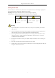
Digital Video Recorder User Manual 1.1 Front Panel Front Panel 1: Figure 1. 1 Front Panel of DS-7100 Please refer to Table 1.1 for the description of the front panel of DS-7100 series DVR. Table 1. 1 Description of Front Panel No. Icon Description 1 Turns red when DVR is powered up. 2 Turns red when data is being read from or written to HDD. 3 Flickers blue when network connection is functioning properly. Front Panel 2: Figure 1.
Digital Video Recorder User Manual Front Panel 3: Figure 1. 3 Front Panel of DS-7200HUHI-F/N Table 1. 3 Description of Front Panel No. Name Function Description POWER STATUS 1 Turns yellow when the device s running. Flickers red when data is being read from or written to HDD, and turns yellow when the SHIFT function is realized. Flickers yellow when network connection is functioning properly. Tx/Rx SHIFT 1/MENU Switches between the numeric or letter input and functions of the composite keys.
Digital Video Recorder User Manual No. Name Function Description Enters letters “WXYZ”; Multi-channel display in live view. Enters numeral “0”; 0/A Shifts the input methods in the editing text field. (Upper and lowercase, alphabet, symbols or numeric input). Navigates between different fields and items in menus. Uses the Up and Down buttons to speed up and slow down the playing of video files in Playback mode. DIRECTION The Left and Right button will select the next and previous record files.
Digital Video Recorder User Manual No. Name Function Description 1/MENU Enters numeral “1”; Accesses the main menu interface. Enters numeral “2”; Enters letters “ABC”; The F1 button when used in a list field will select all items in the list; 2/ABC/F1 Turns on/off PTZ light in PTZ Control mode, and use it to zoom out the image; Switches between main and spot video output in live view or playback mode.
Digital Video Recorder User Manual No. Name Function Description Plays or pauses the playing of video files in Playback mode. Advances the video by a single frame in single-frame Playback mode. Stops/starts auto switch in Auto-switch mode. 5 Power on/off switch. POWER Moves the active selection up and down in a menu. Cycles through different channels in live view mode. 6 JOG SHUTTLE Control Jumps 30s forward/backward in video files in the playback mode.
Digital Video Recorder User Manual No. Name Function Description Navigates between different fields and items in menus. Uses the Up and Down buttons to speed up and slow down the playing of video files in Playback mode. DIRECTION The Left and Right button will select the next and previous record files. 3 Cycles through channels in Live View mode. Control Controls the movement of the PTZ camera in PTZ control mode. Buttons Confirms selection in any of the menu modes. Checks the checkbox.
Digital Video Recorder User Manual No. Name Function Description Presses and holds the button for five seconds to turn off audible key beep. Starts wiper (if applicable) in PTZ control mode. Shows/hides the control interface in playback mode. Switches between single screen and multi-screen mode. PREV/FOCUS- Adjusts the focus in conjunction with the A/FOCUS+ button in PTZ control mode. PTZ/IRIS- Enters the PTZ Control mode. Adjusts the iris of the PTZ camera in PTZ control mode.
Digital Video Recorder User Manual 1.2 IR Remote Control Operations The DVR may also be controlled with the included IR remote control, shown in Figure 1. 6. Batteries (2×AAA) must be installed before operation. Figure 1. 6 Remote Control The keys on the remote control closely resemble the ones found on the front panel. Refer to Table 1. 6, they include: Table 1. 6 Description of the IR Remote Control Buttons No. Name Description Power on/off the device.
Digital Video Recorder User Manual No. Name Description In the Playback mode, the Up and Down button is used to speed up and slow down recorded video. The Left and Right button will select the next and previous record files. In Live View mode, these buttons can be used to cycle through channels. In PTZ control mode, it can control the movement of the PTZ camera. Confirm selection in any of the menu modes. It can also be used to tick checkbox fields.
Digital Video Recorder User Manual 1.3 USB Mouse Operation A regular 3-button (Left/Right/Scroll-wheel) USB mouse can also be used with this DVR. To use a USB mouse: Steps: 1. Plug USB mouse into one of the USB interfaces on the front panel of the DVR. 2. The mouse should automatically be detected. If in a rare case that the mouse is not detected, the possible reason may be that the two devices are not compatible, please refer to the recommended the device list from your provider.
Digital Video Recorder User Manual 1.4 Input Method Description Figure 1. 7 Soft Keyboard Description of the buttons on the soft keyboard: Table 1.
Digital Video Recorder User Manual 1.5 Rear Panel The rear panel vaires according to different models. Please refer to the actual product. The following figures are for reference only. Rear Panel 1: Figure 1. 8 Rear Panel of DS-7100 Table 1. 9 Description of Rear Panel No. Item Description 1 VIDEO IN BNC interface for TVI, and analog video input. 2 HDMI HDMI video output connector. 3 VGA DB15 connector for VGA output. Display local video output and menu. 4 AUDIO OUT RCA connector.
Digital Video Recorder User Manual Rear Panel 3: Figure 1. 10 Rear Panel of DS-7200HGHI-E1/E2 Rear Panel 4: Figure 1. 11 Rear Panel of DS-7200HQHI-F1/N Rear Panel 5: Figure 1. 12 Rear Panel of DS-7200HQHI-F2/N Table 1. 11 Description of Rear Panel No. Item Description 1 VIDEO IN BNC interface for TVI and analog video input. 2 AUDIO IN RCA connector 3 AUDIO OUT RCA connector 4 VGA 5 HDMI HDMI video output connector. 6 USB Port Universal Serial Bus (USB) port for additional devices.
Digital Video Recorder User Manual Rear Panel 6: Figure 1. 13 Rear Panel of DS-7200HUHI-F/N The rear panels of DS-7208HUHI-F1/N and DS-7208HUHI-F2/N provide 8 video input interfaces. The rear panel of DS-7216HUHI-F2/N provides 16 video input interfaces. Table 1. 12 Description of Rear Panel No. Item Description 1 VIDEO IN BNC interface for TVI and analog video input. 2 AUDIO IN RCA connector 3 AUDIO OUT RCA connector. VGA DB15 connector for VGA output. Display local video output and 4 menu.
Digital Video Recorder User Manual Rear Panel 7: Figure 1. 15 Rear Panel of DS-8100HQHI-F8/N The rear panel of DS-8104HQHI-F8/N and DS-8108HQHI-F8/N provide 4 and 8 video input interfaces respectively. Table 1. 13 Description of Rear Panel No. Item Description 1 VIDEO IN BNC interface for TVI and analog video input. VIDEO OUT BNC connector for video output.
Digital Video Recorder User Manual Chapter 2 Getting Started 28
Digital Video Recorder User Manual 2.1 Starting Up and Shutting Down the DVR Purpose: Proper startup and shutdown procedures are crucial to expanding the life of the DVR. Before you start: Check that the voltage of the extra power supply is the same with the DVR’s requirement, and the ground connection is working properly. Starting up the DVR Steps: 1. Check the power supply is plugged into an electrical outlet.
Digital Video Recorder User Manual 2.2 Activating the Device Purpose: For the first-time access, you need to activate the device by setting an admin password. No operation is allowed before activation. You can also activate the device via Web Browser, SADP or Client Software. Steps: 1. Input the same password in the text field of Create New Password and Confirm New Password. Figure 2.
Digital Video Recorder User Manual 2.3 Basic Configuration in Startup Wizard 2.3.1 Configuring the Signal Input Channel Purpose: After the startup and login, the device system enters the Wizard for configuring the signal input. You can also click Menu > Camera > Signal Input Status to configure the signal input. Steps: 1. Check the checkbox to select different signal input types: TVI/CVBS, AHD, and IP (For E series DVR, there is no signal input configuration interface.). 2.
Digital Video Recorder User Manual 2.3.2 Using the Wizard for Basic Configuration Purpose: By default, the Setup Wizard starts once the device has loaded. You can follow it to complete the basic configuration. Selecting the language: Steps: 1. Select the language from the dropdown list. 2. Click Apply button. Figure 2. 6 Language Configuration Operating the Setup Wizard: Steps: 1. The Start Wizard can walk you through some important settings of the device.
Digital Video Recorder User Manual Figure 2. 9 General Network Configuration 2 self-adaptive 10M/100M/1000M network interfaces for DS-8100HQHI-F/N series, with three working modes configurable: multi-address, load balance, network fault tolerance; and 1 self-adaptive 10M/100M/1000M network interface or 1 self-adaptive 10M/100Mbps network interface provided for other models. 4. Click Next button after you configured the basic network parameters. Then you will enter the EZVIZ Cloud P2P interface.
Digital Video Recorder User Manual Figure 2. 11 Set Advanced Network Parameters 6. Click Next button after configuring the advanced network parameters, which will take you to the HDD Management interface as shown in Figure 2.12. Figure 2. 12 HDD Management 7. To initialize the HDD, click the Init button. Initialization will remove all the data saved in the HDD. 8. Click Next button to enter the IP Camera Management interface. 9. Add the IP camera. 1) Click Search to search the online IP Camera.
Digital Video Recorder User Manual Figure 2. 13 IP Camera Management 10. After finishing IP Camera settings, click Next to enter the Record Settings interface. 11. Click the icon , and you can enable the continuous recording or motion detection recording for all channels of the device. Figure 2. 14 Record Settings 12. Click OK to complete the wizard settings.
Digital Video Recorder User Manual 2.4 Login and Logout 2.4.3 User Login Purpose: You have to log in to the device before operating the menu and other functions Steps: 1. Select the User Name in the dropdown list. Figure 2. 15 Login Interface 2. Input Password. 3. Click OK to log in. In the Login interface, for the admin, if you have entered the wrong password for 7 times, the account will be locked for 60 seconds.
Digital Video Recorder User Manual 2.4.4 User Logout Purpose: After logging out, the monitor turns to the live view mode and if you want to perform some operations, you need to enter the user name and password to log in again. Steps: 1. Enter the Shutdown menu. Menu > Shutdown Figure 2. 18 Logout 2. Click Logout. After you have logged out of the system, menu operation on the screen is invalid. It is required to input a user name and password to unlock the system.
Digital Video Recorder User Manual 2.5 Adding and Connecting the IP Cameras 2.5.1 Activating the IP Camera The IP camera connection is not supported by DS-7100 series DVR. Purpose: Before adding the camera, make sure the IP camera to be added is in active status. Steps: 1. Select the Add IP Camera option from the right-click menu in live view mode or click Menu> Camera> IP Camera to enter the IP Camera Management interface.
Digital Video Recorder User Manual Figure 2. 21 Set New Password Create New Password: If the admin password is not used, you must create the new password for the camera and confirm it. STRONG PASSWORD RECOMMENDED–We highly recommend you create a strong password of your own choosing (Using a minimum of 8 characters, including at least three of the following categories: upper case letters, lower case letters, numbers, and special characters.) in order to increase the security of your product.
Digital Video Recorder User Manual of the DVR’s). Or you can click the One-touch Adding button to add all cameras (with the same admin password) from the list. 4. Make sure the camera to add has already been actiavted by setting the admin password, and the admin password of the camera is the same with the DVR’s. (For the encoders with multiple channels only) check the checkbox of Channel Port in the pop-up window, as shown in the following figure, and click OK to add multiple channels. Figure 2.
Digital Video Recorder User Manual Figure 2. 25 Successfully Added IP Cameras Please refer to Chapter 17.1 Specifications for the number of connectable IP cameras for different models. Table 2. 1 Explanation of the icons Icon Explanation Icon Edit basic parameters of the camera Add the detected IP camera. The camera is disconnected; You can click the icon to get the exception information of camera. Play the live video of the connected camera. Upgrade the connected IP camera.
Digital Video Recorder User Manual channel to connect by selecting the channel port No. in the dropdown list. 2. Click OK to save the settings and exit from the editing interface. 3. Drag the horizontal scroll bar to the right side and click the icon to edit the advanced parameters. Figure 2. 27 Network Configuration of the Camera 4. You can edit the network information and the password of the camera. Figure 2. 28 Password Configuration of the Camera 5.
Digital Video Recorder User Manual 2.6 Configuring the Signal Input Channel Purpose: The F1/N, F2/N, and F1/F2 series DVR supports the AHD video input. You must define each analog channel to TVI/CVBS, AHD or IP signal input before connecting the camera. And the channel must be connected with the same video input type which you configure on the menu. Steps: 1. Enter the Signal Input Status interface. Menu > Camera > Signal Input Status 2.
Digital Video Recorder User Manual selected, only the AHD signal input can be connected. For DS-7200HUHI-F/N series, the default TVI/CVBS signal input type also supports the auto detection of 3MP signal. Each two types of the signals can be mixed randomly. In the live view interface, when there is no video signal of the analog channel, the corresponding connectable video signal type message can be displayed on the screen.
Digital Video Recorder User Manual Chapter 3 Live View 45
Digital Video Recorder User Manual 3.1 Introduction of Live View Live view shows you the video image getting from each camera in real time. The DVR will automatically enter Live View mode when powered on. It is also at the very top of the menu hierarchy, thus hitting the ESC many times (depending on which menu you’re on) will bring you to the Live View mode.
Digital Video Recorder User Manual 3.2 Operations in Live View Mode In live view mode, there are many functions provided. The functions are listed below. • Single Screen: show only one screen on the monitor. • Multi-screen: show multiple screens on the monitor simultaneously. • Auto-switch: the screen is auto switched to the next one. And you must set the dwell time for each screen on the configuration menu before enabling the auto-switch. Menu>Configuration>Live View>Dwell Time.
Digital Video Recorder User Manual Figure 3. 1 Right-click Menu 3.2.2 Main/Aux Output Switching Only the DS-7200HQHI-F/N, DS-7200HUHI-F/N, DS-7300HQHI-F/N and DS-8100HQHI-F/N series support Aux/Main output switch. When the HDMI/VGA output is configured as the main output, you can perform the following operation to switch to CVBS output as the main output. Steps: 1. Use the mouse wheel to double-click on the HDMI/VGA output screen, and the following message box pops up: Figure 3.
Digital Video Recorder User Manual Icons / Description Enable/Disable Manual Record Table 3. 4 Description of Quick Setting Toolbar Icons Icons Description Icons Description Instant Playback Mute/Audio on / PTZ Control Digital Zoom Image Settings Close Live View Face Detection Information Instant Playback only shows the record in last five minutes. If no record is found, it means there is no record during the last five minutes. Digital Zoom can zoom in the selected area to the full screen.
Digital Video Recorder User Manual Figure 3. 6 Enable Face Detection You can configure face detection only when it is supported by the connected camera. Move the mouse onto the Information icon to show the real-time stream information, including the frame rate, bit rate, resolution and stream type. Figure 3.
Digital Video Recorder User Manual 3.3 Channel-Zero Encoding This section is not applicable to DS-7100/7200HGHI-E1/E2 series DVR. Purpose: Sometimes you need to get a remote view of many channels in real time from web browser or CMS (Client Management System) software, in order to decrease the bandwidth requirement without affecting the image quality, channel-zero encoding is supported as an option for you. Steps: 1. Enter the Live View Settings interface. Menu> Configuration> Live View 2.
Digital Video Recorder User Manual 3.4 Adjusting Live View Settings Purpose: Live View settings can be customized according to different needs. You can configure the output interface, dwell time for screen to be shown, mute or turning on the audio, the screen number for each channel, etc. Steps: 1. Enter the Live View Settings interface. Menu> Configuration> Live View Figure 3.
Digital Video Recorder User Manual 3.5 Manual Video Quality Diagnostics Purpose: The video quality of the analog channels can be diagnosed manually and you can view the diagnostic results from a list. Steps: 1. Enter the Manual Video Quality Diagnostics interface. Menu> Manual >Manual Video Quality Diagnostics Figure 3. 11 Video Quality Diagnostics 2. Check the checkboxes to select the channels for diagnostics. 3. Click the button Diagnose, and the results will be displayed on a list.
Digital Video Recorder User Manual Chapter 4 PTZ Controls 54
Digital Video Recorder User Manual 4.1 Configuring PTZ Settings Purpose: Follow the procedure to set the parameters for PTZ. The configuring of the PTZ parameters should be done before you control the PTZ camera. Steps: 1. Enter the PTZ Settings interface. Menu >Camera> PTZ Figure 4. 1 PTZ Settings 2. Choose the camera for PTZ setting in the Camera dropdown list. 3. Click the PTZ Parameters button to set the PTZ parameters. Figure 4. 2 PTZ- General 4.
Digital Video Recorder User Manual When the Coaxitron protocol is selected, all the other parameters like the baud rate, data bit, stop bit, parity and flow control are not configurable. 5. (Optional) Click Copy button to copy the settings to the other channels. Select the channels you want to copy to and click OK to return to the PTZ Parameters Settings interface. Figure 4. 3 Copy to Other Channels 6. Click OK to save the settings.
Digital Video Recorder User Manual 4.2 Setting PTZ Presets, Patrols and Patterns Before you start: Please make sure that the presets, patrols and patterns should be supported by PTZ protocols. 4.2.1 Customizing Presets Purpose: Follow the steps to set the Preset location which you want the PTZ camera to point to when an event takes place. Steps: 1. Enter the PTZ Settings interface. Menu>Camera>PTZ Figure 4. 4 PTZ Settings 2.
Digital Video Recorder User Manual Figure 4. 5 PTZ Panel - General 4. Click to enter the preset No. in the corresponding text field. 5. Click the Call Preset button to call it. When the Coaxitron camera/dome connected and the PTZ protocol is selected to HIKVISION-C (Coaxitron), you can call the preset 95 to enter the menu of the connected Coaxitron camera/dome. Use the directional buttons on the PTZ control panel to operate the menu. 4.2.
Digital Video Recorder User Manual Figure 4. 7 Key point Configuration 4. Configure key point parameters, such as the key point No., duration of staying for one key point and speed of patrol. The key point is corresponding to the preset. The Key Point No. determines the order at which the PTZ will follow while cycling through the patrol. The Duration refers to the time span to stay at the corresponding key point. The Speed defines the speed at which the PTZ will move from one key point to the next. 5.
Digital Video Recorder User Manual Figure 4. 9 PTZ Settings 2. Choose pattern number in the dropdown list. 3. Click the Start button and click corresponding buttons in the control panel to move the PTZ camera, and click the Stop button to stop it. The movement of the PTZ is recorded as the pattern. 4.2.6 Calling Patterns Purpose: Follow the procedure to move the PTZ camera according to the predefined patterns. Steps: 1.
Digital Video Recorder User Manual 4.2.7 Customizing Linear Scan Limit Purpose: The Linear Scan can be enabled to trigger the scan in the horizantal direction in the predefined range. This function is supported by some certain models. Steps: 1. Enter the PTZ Settings interface. Menu > Camera > PTZ Figure 4. 11 PTZ Settings 2.
Digital Video Recorder User Manual Figure 4. 12 PTZ Panel - One-touch 3. Click Linear Scan button to start the linear scan and click the Linear Scan button again to stop it. You can click the Restore button to clear the defined left limit and right limit data and the dome needs to reboot to make settings take effect. 4.2.9 One-touch Park Purpose: For some certain model of the speed dome, it can be configured to start a predefined park action (scan, preset, patrol and etc.
Digital Video Recorder User Manual 4.3 PTZ Control Panel To enter the PTZ control panel, there are two ways supported. OPTION 1: In the PTZ Settings interface, click the PTZ button on the lower-right corner which is next to the Back button. OPTION 2: In the Live View mode, you can press the PTZ Control button on the front panel or on the remote control, or choose the PTZ Control icon in the quick setting bar, or select the PTZ Control option in the right-click menu.
Digital Video Recorder User Manual Chapter 5 Recording Settings 64
Digital Video Recorder User Manual 5.1 Configuring Encoding Parameters Before you start: 1. Make sure that the HDD has already been installed. If not, please install a HDD and initialize it. (Menu>HDD>General) Figure 5. 1 HDD- General 2. Click Advanced tab to check the storage mode of the HDD. (Menu>HDD>Advanced) 1) If the HDD mode is Quota, please set the maximum record capacity. For detailed information, see Chapter 13.4 Configuring Quota Mode. 2) If the HDD mode is Group, you should set the HDD group.
Digital Video Recorder User Manual detection of 3MP signal. If the configured encoding resolution conflicts with the resolution of the front-end camera, the encoding parameters will adjust automatically to meet the front-end camera. E.g., if the resolution of the front-end camera is 720p, then the encoding resolution of the main stream will adjust to 720p automatically.
Digital Video Recorder User Manual select sub-stream, you can record for a longer time with the same storage space. The Redundant Record option is only available when the HDD mode is Group. Redundant HDD is required for the redundant record function. For detailed information, see Chapter 12.3.2 Setting HDD Property. For network cameras, the parameters of Main Stream (Event) are not editable. 5. Click Apply to save the settings. 6.
Digital Video Recorder User Manual 5.2 Configuring Recording Schedule The DS-7100 models support continuous, motion and event triggered recording types, and other models support continuous, alarm, motion, motion | alarm, motion & alarm, event and POS triggered recording types. In this chapter, we take the record schedule procedure as an example, and the same procedure can be applied to configure schedule for both continuous recording.
Digital Video Recorder User Manual Figure 5. 8 Edit Schedule- All Day 4) To arrange other schedule, leave the All Day checkbox blank and set the Start/End time. Figure 5. 9 Edit Schedule- Set Time Period Up to 8 periods can be configured for each day. And the time periods cannot be overlapped with each other.
Digital Video Recorder User Manual Figure 5. 11 Draw the Schedule 2) Click and drag the mouse on the schedule. 3) Click on the other area except for the schedule table to finish and exit from the drawing. You can repeat step 4 to set schedule for other channels. If the settings can also be used to other channels, click Copy, and then choose the channel to which you want to copy to. 5. Click Apply in the Record Schedule interface to save the settings.
Digital Video Recorder User Manual 5.3 Configuring Motion Detection Recording Purpose: Follow the steps to set the motion detection parameters. In the live view mode, once a motion detection event takes place, the DVR can analyze it and do many actions to handle it. Enabling motion detection function can trigger certain channels to start recording, or trigger full screen monitoring, audio warning, notifying the surveillance center, sending email and so on. Steps: 1. Enter the Motion Detection interface.
Digital Video Recorder User Manual 5.4 Configuring Alarm Triggered Recording Purpose: Follow the procedure to configure alarm triggered recording. Steps: 1. Enter the Alarm Setting interface. Menu> Configuration> Alarm Figure 5. 15 Alarm Settings 2. Click the Alarm Input tab. Figure 5. 16 Alarm Settings- Alarm Input 1) 2) 3) Select Alarm Input number and configure alarm parameters. Choose N.O (normally open) or N.C (normally closed) for alarm type. Check the checkbox of Setting. 4) Click the button.
Digital Video Recorder User Manual Figure 5. 18 Copy Alarm Input 3. Configure the schedule. Please refer to the step 4 of Chapter 5.2 Configuring Recording Schedule, while you may choose Alarm as the record type.
Digital Video Recorder User Manual 5.5 Configuring Event Recording Purpose: The event triggered recording can be configured through the menu.
Digital Video Recorder User Manual Figure 5. 20 Set Trigger Camera of VCA Alarm The PTZ Linking function is only available for the VCA settings of IP cameras. 5. Enter Record Schedule Settings interface (Menu> Record> Schedule>Record Schedule), and then set Event as the record type. For details, see step 2 in Chapter 5.2 Configuring Record Schedule.
Digital Video Recorder User Manual 5.6 Configuring Manual Recording Purpose: Follow the steps to set parameters for the manual record. Using manual record, you don’t need to set a schedule for recording. Steps: 1. Enter the Manual Record interface. Menu> Manual Figure 5. 21 Manual Record 2. Enable manual record. Click the status icon Or click the status icon 3. Disable manual record. Click the status icon Or click the status icon before camera number to change it to .
Digital Video Recorder User Manual 5.7 Configuring Holiday Recording Purpose: Follow the steps to configure the record schedule on holiday for that year. You may want to have different plan for recording on holiday. Steps: 1. Enter the Record setting interface. Menu>Record 2. Choose Holiday on the left bar. Figure 5. 22 Holiday Settings 3. Enable Edit Holiday schedule. 1) Click to enter the Edit interface. Figure 5. 23 Edit Holiday Settings 2) Check the checkbox of Enable.
Digital Video Recorder User Manual Figure 5. 24 Edit Schedule- Holiday Up to 8 periods can be configured for each day. And the time periods cannot be overlapped each other. In the time table of the channel, both holiday schedule and normal day schedule are displayed. Repeat the above step 4 to set Holiday schedule for other channels. If the holiday schedule can also be used to other channels, click Copy and choose the channel you want to apply the settings.
Digital Video Recorder User Manual 5.8 Configuring Redundant Recording Purpose: Enabling redundant recording, which means saving the record files not only in the R/W HDD but also in the redundant HDD, will effectively enhance the data safety and reliability. Before you start: You must set the Storage mode in the HDD advanced settings to Group before you set the HDD property to Redundant. For detailed information, please refer to Chapter 13.3 Managing HDD Group.
Digital Video Recorder User Manual Figure 5. 27 Encoding Parameters 2) 3) 4) 5) Select Camera you want to configure. Check the checkbox of Redundant Record. Click Apply to save settings. If the encoding parameters can also be used to other channels, click Copy and choose the channel you want to apply the settings.
Digital Video Recorder User Manual 5.9 Configuring HDD Group Purpose: You can group the HDDs and save the record files in certain HDD group. Steps: 1. Enter HDD setting interface. Menu>HDD>Advanced 2. Select Advanced on the left bar. Check whether the storage mode of the HDD is Group. If not, set it to Group. For detailed information, please refer to Chapter 13.3 Managing HDD Group. 3. Select General in the left bar. Click to enter editing interface. 4. Configuring HDD group.
Digital Video Recorder User Manual 5.10 Files Protection Purpose: You can lock the recorded files or set the HDD property to Read-only to protect the record files from being overwritten. Protect file by locking the record files Steps: 1. Enter Export Settings interface. Menu> Export Figure 5. 29 Export 2. Select the channels you want to investigate by checking the checkbox to . 3. Configure the record mode, record type, file type, start time and end time. 4. Click Search to show the results. Figure 5.
Digital Video Recorder User Manual Group. Steps: 1. Enter HDD setting interface. Menu> HDD Figure 5. 31 HDD General 2. Click to edit the HDD you want to protect. Figure 5. 32 HDD General- Editing 3. Set the HDD to Read-only. 4. Click OK to save settings and back to the upper level menu. You cannot save any files in a Read-only HDD. If you want to save files in the HDD, change the property to R/W. If there is only one HDD and is set to Read-only, the DVR cannot record any files.
Digital Video Recorder User Manual 5.11 Configuring 1080P Lite Purpose: When the 1080P Lite Mode is enabled, the encoding resolution at 1080P Lite (real-time) is supported. If not, up to 1080P (non-real-time) is supported. This section is appplicable to DS-8100HQHI-F/N series DVR only. DS-7100HQHI-F/N, DS-7200HQHI-F/N, DS-7300HQHI-F/N Task1: Enabling the 1080P Lite Mode Steps: 1. Enter the Record menu Menu > Record 2. Click Advanced to enter the advanced interface. Figure 5. 33 Advanced Interface 3.
Digital Video Recorder User Manual Chapter 6 Playback 85
Digital Video Recorder User Manual 6.1 Playing Back Record Files 6.1.1 Instant Playback Purpose: Play back the recorded video files of a specific channel in the live view mode. Channel switch is supported. Instant playback by channel Steps: Choose a channel in live view mode and click the button in the quick setting toolbar. In the instant playback mode, only record files recorded during the last five minutes on this channel will be played back. Figure 6. 1 Instant Playback Interface 6.1.
Digital Video Recorder User Manual Figure 6. 2 Right-click Menu under Live View Playback by Time Purpose: Play back video files recorded in specified time duration. Multi-channel simultaneous playback and channel switch are supported. Steps: 1. Enter Playback interface. Menu>Playback 2. Check the checkbox of channel(s) in the channel list and then double-click to select a date on the calendar. Figure 6.
Digital Video Recorder User Manual Figure 6. 4 Playback Interface Select the channel(s) if you want to switch playback to another channel or execute simultaneous playback of multiple channels. Figure 6. 5 Toolbar of Playback Button / / Table 6.
Digital Video Recorder User Manual Steps: 1. Enter the Playback interface. Menu>Playback 2. Click and select to enter the Event Playback interface. 3. Select Alarm Input, Motion, VCA as the event type, and specify the start time and end time for search. Figure 6. 6 Video Search by Motion Detection 4. Click Search, and the record files matching the search conditions will be displayed on a list. 5. Select and click button to play back the record files.
Digital Video Recorder User Manual Figure 6. 8 Interface of Playback by Event Pre-play and post-play can be configured for the playback of event triggered record files. Pre-play: The time you set to play back before the event. For example, when an alarm triggered the recording at 10:00, if you set the pre-play time as 5 seconds, the video plays back from 9:59:55. Post-play: The time you set to play back after the event.
Digital Video Recorder User Manual Click Click button to add default tag. button to add customized tag and input tag name. Figure 6. 10 Add Tag Max. 64 tags can be added to a single video file. 3. Tag management. Click button to check, edit and delete tag(s). Figure 6. 11 Tag Management Interface Steps: 1. Select Tag from the drop-down list in the Playback interface. 2. Choose channels, edit start time and end time, and then click Search to enter Search Result interface.
Digital Video Recorder User Manual Figure 6. 12 Video Search by Tag 3. Click button to play back the file. You can click the Back button to return to the search interface. Pre-play and post-play can be configured. You can click or button to select the previous or next tag. Please refer to Table 6.1 for the description of buttons on the toolbar. 6.1.5 Playing Back by Smart Search Purpose: The smart playback function provides an easy way to get through the less effective information.
Digital Video Recorder User Manual Figure 6. 14 Smart Playback Interface 4. Select a date in the calendar and click the button to play. Refer to Table 6.2 for the descriptions of the buttons on the Smart Playback Toolbar. Table 6.
Digital Video Recorder User Manual Play Related Video at: Set the speed to play the related video. Max. 8/4/2/1 are selectable. Pre-play and post-play is not available for the motion event type. 7. Click to search and play the matched video files. 8. (Optional) You can click to filter the searched video files by setting the target characters, including the gender and age of the human and whether he/she wears glasses. Figure 6.
Digital Video Recorder User Manual Figure 6. 18 Result of System Log Search 3. Choose a log with record file and click button to enter Playback interface. If there is no record file at the time point of the log, the message box “No result found” will pop up. 4. Playback management. The toolbar in the bottom part of Playback interface can be used to control playing process. Figure 6. 19 Interface of Playback by Log 6.1.
Digital Video Recorder User Manual Figure 6. 20 Interface of Sub-periods Playback According to the defined number of split-screens, the video files on the selected date can be divided into average segments for playback. E.g., if there are video files existing between 16:00 and 22:00, and the 6-screen display mode is selected, then it can play the video files for 1 hour on each screen simultaneously. 6.1.
Digital Video Recorder User Manual 6.2 Auxiliary Functions of Playback 6.2.1 Playing Back Frame by Frame Purpose: Play video files frame by frame, in order to check image details of the video when abnormal events happen. Steps: 1. Go to Playback interface and click button until the speed changes to Single frame. 2. One click on the playback screen represents playback or adverse playback of one frame. You can use button in toolbar to stop the playing. 6.2.2 Digital Zoom Steps: 1.
Digital Video Recorder User Manual Figure 6. 23 4-ch Synchronous Playback Interface 3. Click to play back the record files reversely.
Digital Video Recorder User Manual Chapter 7 Backup 99
Digital Video Recorder User Manual 7.1 Backing up Record Files Before you start: Please insert the backup device(s) into the device. 7.1.1 Backing up by Normal Video Search Purpose: The record files can be backed up to various devices, such as USB devices (USB flash drives, USB HDDs, USB writer), SATA writer and e-SATA HDD. Backup using USB flash drives and USB HDDs Steps: 1. Enter Export interface. Menu>Export>Normal 2. Select the cameras to search. 3.
Digital Video Recorder User Manual Figure 7. 2 Result of Normal Video Search for Backup 5. Select video files from the Chart or List to export, and click the button Export to enter the Export interface. You can also click Export All to select all the video files for backup and enter the Export interface. Figure 7. 3 Export by Normal Video Search using USB Flash Drive 6.
Digital Video Recorder User Manual Figure 7. 5 Export Finished The backup of video files using USB writer or SATA writer has the same operating instructions. Please refer to steps described above. 7.1.2 Backing up by Event Search Purpose: Back up event-related record files using USB devices (USB flash drives, USB HDDs, USB writer), SATA writer or eSATA HDD. Quick Backup and Normal Backup are supported. Steps: 1. Enter Export interface. Menu > Export > Event 2. Select the cameras to search. 3.
Digital Video Recorder User Manual Figure 7. 7 Result of Event Search 6. Export the video files. Please refer to step5 of Chapter 7.1.1 Backing up by Normal Video Search for details. 7.1.3 Backing up Video Clips Purpose: You may also select video clips in playback mode to export directly during Playback, using USB devices (USB flash drives, USB HDDs, USB writer), or SATA writer. Steps: 1. Enter Playback interface. 2. During playback, use buttons 3.
Digital Video Recorder User Manual Figure 7. 9 Storage Device Management 2. Backup device management. Click New Folder button if you want to create a new folder in the backup device. Select a record file or folder in the backup device and click button if you want to delete it. Click Erase button if you want to erase the files from a re-writable CD/DVD. Click Format button to format the backup device. If the inserted storage device is not recognized: • Click the Refresh button. • Reconnect device.
Digital Video Recorder User Manual Chapter 8 Alarm Settings 105
Digital Video Recorder User Manual 8.1 Setting Motion Detection Steps: 1. Enter Motion Detection interface of Camera Management and choose a camera you want to set up motion detection. Menu> Camera> Motion Figure 8. 1 Motion Detection Setup Interface 2. Set detection area and sensitivity. Check checkbox to enable motion detection. Use the mouse to draw detection area(s) or click Full Screen to set the detection area to be the full screen and drag the sensitivity bar to set sensitivity.
Digital Video Recorder User Manual Time periods shall not be repeated or overlapped. Figure 8. 4 Set Arming Schedule of Motion Detection 5. Click Linkage Action tab to set up alarm response actions of motion alarm (please refer to Chapter 8.7 Setting Alarm Response Actions). Repeat the above steps to set up arming schedule of other days of a week. Click the OK button to complete the motion detection settings of the channel. 6.
Digital Video Recorder User Manual 8.2 Setting Sensor Alarms Purpose: Set up handling method of an external sensor alarm. Steps: 1. Enter Alarm Settings of System Configuration and select an alarm input. Menu> Configuration> Alarm Select Alarm Input tab to enter Alarm Input Settings interface. Figure 8. 5 Alarm Status Interface of System Configuration 2. Set the handling method of the selected alarm input. Check the Enable checkbox and click button to set its alarm response actions. Figure 8.
Digital Video Recorder User Manual Figure 8. 7 Set Arming Schedule of Alarm Input 5. Select Linkage Action tab to set up alarm response actions of the alarm input (please refer to Chapter 8.7 Setting Alarm Response Actions). Repeat the above steps to set up arming schedule of other days of a week. You can also use Copy button to copy an arming schedule to other days. 6. If necessary, select PTZ Linking tab and set PTZ linkage of the alarm input.
Digital Video Recorder User Manual Figure 8.
Digital Video Recorder User Manual 8.3 Detecting Video Loss Purpose: Detect video loss of a channel and take alarm response action(s). Steps: 1. Enter Video Loss interface of Camera Management and select a channel you want to detect. Menu> Camera> Video Loss Figure 8. 10 Video Loss Setup Interface 2. Set up handling method of video loss. Check the checkbox of Enable Video Loss Alarm. Click button to set up handling method of video loss. 3. Set arming schedule of the channel.
Digital Video Recorder User Manual 8.4 Detecting Video Tampering Purpose: Trigger alarm when the lens is covered and take alarm response action(s). Steps: 1. Enter Video Tampering interface of Camera Management and select a channel you want to detect video tampering. Menu> Camera> Video Tampering Detection Figure 8. 12 Video Tampering Interface 2. Check the checkbox of Enable Video Tampering Detection. 3. Drag the sensitivity bar and choose a proper sensitivity level. 4.
Digital Video Recorder User Manual 8.5 Setting All-day Video Quality Diagnostics Purpose: The device provides two ways to diagnose the video quality: manual and all-day. Perform the following steps to set the threshold of the diagnosing and the linkage actions. Steps: 1. Enter Video Quality Diagnostics Settings interface of Camera Management and select a channel you want to detect video tampering. Menu> Camera> Video Quality Diagnostics Figure 8. 14 Video Quality Diagnostics Interface 2.
Digital Video Recorder User Manual Figure 8. 15 Set Arming Schedule of Video Quality Diagnostics 3) Select Linkage Action tab to set alarm response actions of video quality diagnostics alarm (please refer to Chapter 8.7 Setting Alarm Response Actions). Repeat the above steps to set arming schedule of other days of a week. You can also use Copy button to copy an arming schedule to other days. 4) Click the OK button to complete the video quality diagnostics settings of the channel. 5.
Digital Video Recorder User Manual 8.6 Handling Exceptions Purpose: Exception settings refer to the handling method of various exceptions, e.g. • HDD Full: The HDD is full. • HDD Error: Writing HDD error, unformatted HDD, etc. • Network Disconnected: Disconnected network cable. • IP Conflicted: Duplicated IP address. • Illegal Login: Incorrect user ID or password. • Input/Recording Resolution Mismatch: The input resolution is smaller than the recording resolution.
Digital Video Recorder User Manual Figure 8. 18 Detailed Event 3. Set the alarm linkage actions. For details, see Chapter 8.7 Setting Alarm Response Actions. 4. Click Apply to save the settings.
Digital Video Recorder User Manual 8.7 Setting Alarm Response Actions Purpose: Alarm response actions will be activated when an alarm or exception occurs, including Full Screen Monitoring, Audible Warning (buzzer), Notify Surveillance Center, Send Email and Trigger Alarm Output. Full Screen Monitoring When an alarm is triggered, the local monitor (HDMI, VGA or CVBS monitor) displays in full screen the video image from the alarming channel configured for full screen monitoring.
Digital Video Recorder User Manual Figure 8. 20 Set Arming Schedule of Alarm Output 3. Repeat the above steps to set arming schedule of other days of a week. You can also click Copy button to copy an arming schedule to other days. Click the OK button to complete the arming schedule setting of alarm output. 4. Click the Apply button to save the settings.
Digital Video Recorder User Manual Chapter 9 POS Configuration 119
Digital Video Recorder User Manual This chapter is applicable to DS-7300HQHI-F/N and DS-8100HQHI-F/N series DVR only. 9.1 Configuring POS Settings Steps: 1. Enter the POS settings interface. Menu > Configuration > POS> POS Settings 2. Select the POS from the drop-down list. Up to 8 POS units are selectable. 3. Check the checkbox to enable the POS feature. Figure 9. 1 POS Settings 4. Select the POS protocol to Universal Protocol, EPSON or AVE.
Digital Video Recorder User Manual Figure 9. 3 TCP Connection Settings UDP Connection When using UDP connection, the port must be set from 0 to 65535, and the port for each POS machine must be unique. Figure 9. 4 UDP Connection Settings USB->RS-232 Connection Configure the port parameters of USB-to-RS-232 convertor, including the serial number of port, baud rate, data bit, stop bit, parity and flow ctrl.
Digital Video Recorder User Manual Multicast Connection When connecting the DVR and the POS machine via Multicast protocol, set the multicast address and port. Figure 9. 7 Multicast Settings Sniff Connection Connect the DVR and the POS machine via Sniff. Configure the source address and destination address settings. Figure 9. 8 Sniff Settings 6. Set other parameters of characters overly. 1) Select the character encoding format from the drop-down list.
Digital Video Recorder User Manual Figure 9.
Digital Video Recorder User Manual 9.2 Configuring Overlay Channel Purpose: You can assign the POS machine to corresponding channel on which you want to overlay. Steps: 1. Enter the POS settings interface. Menu > Configuration > POS> Overlay Channel 2. Click to select an analog or IP camera from the camera list on the right, and then click a POS item from the POS list you want to overlay on the selected camera. Click or to go to the previous or next page of cameras. Figure 9.
Digital Video Recorder User Manual 9.3 Configuring POS Alarm Purpose: Set the POS alarm parameters to trigger certain channels to start recording, or trigger full screen monitoring, audio warning, notifying the surveillance center, sending email and so on. Steps: 1. Enter the POS settings interface. Menu > Configuration > POS> POS Settings 2. Follow the steps in Chapter 9.1-9.2 to configure the POS settings. 3. Click to enter the alarm settings interface. Figure 9. 12 Set Trigger Cameras of POS 4.
Digital Video Recorder User Manual 8. Select PTZ Linking tab and set PTZ linkage of the POS alarm. Set PTZ linking parameters and click the OK button to complete the settings of the alarm input. Please check whether the PTZ or speed dome supports PTZ linkage. Figure 9. 14 Set PTZ Linking 9. Click OK to save the settings.
Digital Video Recorder User Manual Chapter 10 VCA Alarm 127
Digital Video Recorder User Manual Purpose: The DVR can receive the VCA alarm (line crossing detection, intrusion detection, sudden scene change detection and audio exception detection) sent by analog camera, and the VCA detection must be enabled and configured on the camera settings interface first. All other VCA detection features must be supported by the connected IP camera. The DS-7100 series DVR do not support the VCA alarm.
Digital Video Recorder User Manual 10.2 Vehicle Detection Purpose: Vehicle Detection is available for the road traffic monitoring. In Vehicle Detection, the passed vehicle can be detected and the picture of its license plate can be captured. You can send alarm signal to notify the surveillance center and upload the captured picture to FTP server. Steps: 1. Enter the VCA settings interface. Menu> Camera> VCA 2. Select the camera to configure the VCA.
Digital Video Recorder User Manual Please refer to the User Manual of Network Camera for the detailed instructions for the vehicle detection. 10.3 Line Crossing Detection Purpose: This function can be used for detecting people, vehicles and objects cross a set virtual line. The line crossing direction can be set as bidirectional, from left to right or from right to left. And you can set the duration for the alarm response actions, such as full screen monitoring, audible warning, etc. Steps: 1.
Digital Video Recorder User Manual Figure 10. 6 Draw Line for Line Crossing Detection 8. Click Apply to activate the settings. The sudden scene change detection and the line crossing detection cannot be enabled at the same channel.
Digital Video Recorder User Manual 10.4 Intrusion Detection Purpose: Intrusion detection function detects people, vehicle or other objects which enter and loiter in a pre-defined virtual region, and some certain actions can be taken when the alarm is triggered. Steps: 1. Enter the VCA settings interface. Menu> Camera> VCA 2. Select the camera to configure the VCA. You can click the checkbox of Save VCA Picture to save the captured pictures of VCA detection. 3.
Digital Video Recorder User Manual Figure 10. 8 Draw Area for Intrusion Detection 8. Click Apply to save the settings. The sudden scene change detection and the intrusion detection cannot be enabled at the same channel.
Digital Video Recorder User Manual 10.5 Region Entrance Detection Purpose: Region entrance detection function detects people, vehicle or other objects which enter a pre-defined virtual region from the outside place, and some certain actions can be taken when the alarm is triggered. Steps: 1. Enter the VCA settings interface. Menu> Camera> VCA 2. Select the camera to configure the VCA. You can click the checkbox of Save VCA Picture to save the captured pictures of VCA detection. 3.
Digital Video Recorder User Manual detection. Up to 4 rules can be configured. 10.7 Loitering Detection Purpose: Loitering detection function detects people, vehicle or other objects which loiter in a pre-defined virtual region for some certain time, and a series of actions can be taken when the alarm is triggered. Please refer to the Chapter 9.4 Intrusion Detection for operating steps to configure the loitering detection.
Digital Video Recorder User Manual Please refer to the Chapter 9.4 Intrusion Detection for operating steps to configure the parking detection. The Threshold[5s-20s] in the Rule Settings defines the time of the vehicle parking in the region. If you set the value as 10, alarm is triggered after the vehicle stay in the region for 10s. Up to 4 rules can be configured. 10.
Digital Video Recorder User Manual Figure 10. 10 Set Audio Exception Detection Rules 1) 2) 6. Check the checkbox of Audio Loss Exception to enable the audio loss detection function. Check the checkbox of Sudden Increase of Sound Intensity Detection to detect the sound steep rise in the surveillance scene. You can set the detection sensitivity and threshold for sound steep rise. Sensitivity: Range [1-100], the smaller the value is, the more severe the change should be to trigger the detection.
Digital Video Recorder User Manual Chapter 11 VCA Search 138
Digital Video Recorder User Manual With the configured VCA detection, the device supports the VCA search for the behavior search, face search, plate search, people counting and heat map results. The DS-7100 series DVR do not support the VCA search. 11.1 Face Search Purpose: When there are detected face picture captured and saved in HDD, you can enter the Face Search interface to search the picture and play the picture related video files according to the specified conditions.
Digital Video Recorder User Manual Figure 11. 2 Face Search Interface 7. Play the face picture related video file. You can double click on a face picture to play its related video file in the view window on the top right, or select a picture item and click to play it. You can also click to stop the playing, or click / to play the previous/next file. 8.
Digital Video Recorder User Manual 2. Select the camera (s) for the behavior search. 3. Specify the start time and end time for searching the matched pictures. Figure 11. 4 Behavior Search Interface 4.
Digital Video Recorder User Manual 11.3 Plate Search Purpose: You can search and view the matched captured vehicle plate picture and related information according to the plate searching conditions including the start time/end time, country and plate No.. Steps: 1. Enter the Plate Search interface. Menu>VCA Search> Plate Search 2. Select the camera (s) for the plate search. 3. Specify the start time and end time for searching the matched plate pictures. Figure 11. 6 Plate Search 4.
Digital Video Recorder User Manual Figure 11. 7 People Counting Interface 6. You can click the Export button to export the statistics report in excel format.
Digital Video Recorder User Manual 11.5 Heat Map Purpose: Heat map is a graphical representation of data represented by colors. The heat map function is usually used to analyze the visit times and dwell time of customers in a configured area. The heat map function must be supported by the connected IP camera and the corresponding configuration must be set. Steps: 1. Enter the Heat Map interface. Menu>VCA Search> Heat Map 2. Select the camera for the heat map processing. 3.
Digital Video Recorder User Manual Chapter 12 Network Settings 145
Digital Video Recorder User Manual 12.1 Configuring General Settings Purpose: Network settings must be properly configured before you operate DVR over network. Steps: 1. Enter the Network Settings interface. Menu > Configuration > Network Figure 12.
Digital Video Recorder User Manual 12.2 Configuring Advanced Settings 12.2.1 Configuring PPPoE Settings Purpose: The DVR also allows access by Point-to-Point Protocol over Ethernet (PPPoE). Steps: 1. Enter the Network Settings interface. Menu > Configuration > Network 2. Select the PPPoE tab to enter the PPPoE Settings interface. Figure 12. 2 PPPoE Settings Interface 3. Check the Enable PPPoE checkbox to enable this feature. 4. Enter User Name and Password for PPPoE access.
Digital Video Recorder User Manual 7. Click the Apply button to save and exit the interface. After configuration, you can access and manage the DVR by your mobile phone on which the EZVIZ Cloud P2P application is installed or by the website (www.ezviz7.com). For more operation instructions, please refer to the help file on the official website (www.ezviz7.com). 12.2.
Digital Video Recorder User Manual Figure 12. 6 PeanutHull Settings Interface • NO-IP: Enter the account information in the corresponding fields. Refer to the DynDNS settings. 1) Enter Server Address for NO-IP. 2) In the Device Domain Name text field, enter the domain obtained from the NO-IP website (www.no-ip.com). 3) Enter the User Name and Password registered in the NO-IP website. Figure 12. 7 NO-IP Settings Interface • HiDDNS: 1) The Server Address of the HiDDNS server appears by default: www.
Digital Video Recorder User Manual Figure 12. 9 Login Interface 2) Click to register an account if you do not have one and use the account to log in. Figure 12. 10 Register an Account 3) In the Device Management interface, click to register the device. Figure 12. 11 Register the Device 4) Input Device Serial No., Device Domain (Device Name) and HTTP Port. And click OK to add the device.
Digital Video Recorder User Manual via web browser or Client Software with the Device Domain (Device Name). OPTION 1: Access the Device via Web Browser Open a web browser, and enter http://www.hik-online.com/alias in the address bar. Alias refers to the Device Domain on the device or the Device Name on the HiDDNS server. Example: http://www.hik-online.com/nvr If you mapped the HTTP port on your router and changed it to port No. except 80, you have to enter http://www.hik-online.
Digital Video Recorder User Manual DVR is connected to a public network, you should use a NTP server that has a time synchronization function, such as the server at the National Time Center (IP Address: 210.72.145.44). If the DVR is set in a more customized network, NTP software can be used to establish a NTP server used for time synchronization. 12.2.
Digital Video Recorder User Manual Figure 12. 16 External Port Settings Dialog Box 2) Click Apply button to save the settings. 3) You can click Refresh button to get the latest status of the port mapping. Figure 12. 17 UPnP™ Settings Finished-Manual 12.2.6 Configuring More Settings Steps: 1. Enter the Network Settings interface. Menu > Configuration > Network 2. Select the More Settings tab to enter the More Settings interface. Figure 12. 18 More Settings Interface 3.
Digital Video Recorder User Manual The Server Port should be set to the range of 2000-65535 and it is used for remote client software access. The HTTP port is used for remote IE access. Figure 12. 19 Configure More Settings 4. Click the Apply button to save and exit the interface. 12.2.7 Configuring HTTPS Port Purpose: HTTPS provides authentication of the web site and associated web server that one is communicating with, which protects against Man-in-the-middle attacks.
Digital Video Recorder User Manual Figure 12. 21 Create Self-signed Certificate 2) Enter the country, host name/IP, validity and other information. 3) Click OK to save the settings. OPTION 2: Create the authorized certificate 1) Click the Create button to create the certificate request. 2) Download the certificate request and submit it to the trusted certificate authority for signature. 3) After receiving the signed valid certificate, import the certificate to the device. 5.
Digital Video Recorder User Manual Figure 12. 23 Email Settings Interface 3. Configure the following Email settings: Enable Server Authentication (optional): Check the checkbox to enable the server authentication feature. User Name: The user account of sender’s Email for SMTP server authentication. Password: The password of sender’s Email for SMTP server authentication. SMTP Server: The SMTP Server IP address or host name (e.g., smtp.263xmail.com). SMTP Port: The SMTP port.
Digital Video Recorder User Manual Figure 12. 25 Network Traffic Interface 2. You can view the sending rate and receiving rate information on the interface. The traffic data is refreshed every 1 second.
Digital Video Recorder User Manual 12.4 Configuring Network Detection Purpose: You can obtain network connecting status of DVR through the network detection function, including network delay, packet loss, etc. 12.4.1 Testing Network Delay and Packet Loss Steps: 1. Enter the Network Traffic interface. Menu > Maintenance > Net Detect 2. Click the Network Detection tab to enter the Network Detection interface. Figure 12. 26 Network Detection Interface 3. Select a NIC to test network delay and packet loss.
Digital Video Recorder User Manual Figure 12. 28 Packet Export Attention Up to 1M data can be exported each time.
Digital Video Recorder User Manual 12.4.3 Checking Network Status Purpose: You can also check the network status and quick set the network parameters in this interface. Steps: 1. Enter the Network Traffic interface. Menu > Maintenance > Net Detect 2. Click the Network Detection tab to enter the Network Detection interface. 3. Click Status on the right bottom of the interface. Figure 12. 29 Checking Network Status If the network is normal the following message box pops out. Figure 12.
Digital Video Recorder User Manual Steps: 1. Enter the Network Statistics interface. Menu > Maintenance> Net Detect 2. Click the Network Stat. tab to enter the Network Statistics interface. Figure 12. 32 Network Stat. Interface 3. View the bandwidth of Remote Live View, bandwidth of Remote Playback, and bandwidth of Net Total Idle. 4. Click Refresh button to get the latest bandwidth statistics.
Digital Video Recorder User Manual Chapter 13 HDD Management 162
Digital Video Recorder User Manual 13.1 Initializing HDDs Purpose: A newly installed hard disk drive (HDD) must be initialized before it can be used with your DVR. Steps: 1. Enter the HDD Information interface. Menu > HDD > General Figure 13. 1 HDD Information Interface 2. Select HDD to be initialized. 3. Click the Init button. Figure 13. 2 Confirm Initialization 4. Select the OK button to start initialization. Figure 13. 3 Start Initialization 5.
Digital Video Recorder User Manual 13.2 Managing Network HDD Purpose: You can add the allocated NAS or disk of IP SAN to DVR, and use it as network HDD. Steps: 1. Enter the HDD Information interface. Menu > HDD>General Figure 13. 6 HDD Information Interface 2. Click the Add button to enter the Add NetHDD interface, as shown in Figure 13. 7. Figure 13. 7 HDD Information Interface 3. Add the allocated NetHDD. 4. Select the type to NAS or IP SAN. 5. Configure the NAS or IP SAN settings.
Digital Video Recorder User Manual Figure 13. 8 Add NAS Disk • Add IP SAN: 1) 2) 3) 4) Enter the NetHDD IP address in the text field. Click the Search button to the available IP SAN disks. Select the IP SAN disk from the list shown below. Click the OK button to add the selected IP SAN disk. Up to 8 IP SAN disks can be added. Figure 13. 9 Add IP SAN Disk 5) After having successfully added the NAS or IP SAN disk, return to the HDD Information menu. The added NetHDD will be displayed in the list.
Digital Video Recorder User Manual 13.3 Managing HDD Group 13.3.1 Setting HDD Groups Purpose: Multiple HDDs can be managed in groups. Video from specified channels can be recorded onto a particular HDD group through HDD settings. Steps: 1. Enter the Storage Mode interface. Menu > HDD > Advanced 2. Set the Mode to Group, as shown in Figure 13. 11. Figure 13. 11 Storage Mode Interface 3. Click the Apply button and the following Attention box will pop up. Figure 13. 12 Attention for Reboot 4.
Digital Video Recorder User Manual Figure 13. 14 Confirm HDD Group Settings 9. In the pop-up Attention box, click the Yes button to finish the settings. 13.3.2 Setting HDD Property Purpose: The HDD property can be set to redundancy, read-only or read/write (R/W). Before setting the HDD property, please set the storage mode to Group (refer to step1-4 of Chapter 13.3.1 Setting HDD Groups).
Digital Video Recorder User Manual 13.4 Configuring Quota Mode Purpose Each camera can be configured with allocated quota for the storage of recorded files. Steps 1. Enter the Storage Mode interface. Menu > HDD > Advanced 2. Set the Mode to Quota, as shown in Figure 13. 16. The DVR must be rebooted to enable the changes to take effect. Figure 13. 16 Storage Mode Settings Interface 3. Select a camera for which you want to configure quota. 4. Enter the storage capacity in the text field of Max.
Digital Video Recorder User Manual 13.5 Configuring Cloud Storage Purpose The cloud storage facilitates you to upload and download the recorded files at any time and any place, which can highly enhance the efficiency. Cloud storage is only applicable to HQHI-F/N and HUHI-F/N series DVR. Steps 1. Enter the Cloud Storage interface Menu > HDD > General > Cloud Storage 2. Check the Enable Cloud checkbox to enable the feature. 3.
Digital Video Recorder User Manual Figure 13. 19 Record Schedule The POS recording is supported by DS-7300HQHI-F/N and DS-8100HQHI-F/N series DVR only. 8. Upload the event triggered recording files to the cloud storage. 1) Back to enter the cloud storage interface, and select the camera you have set in the recording schedule interface. 2) Select the upload type in the Upload Type text filed. 3) Check the Enable Event Upload checkbox. 4) Click Apply to finish the settings. Figure 13.
Digital Video Recorder User Manual 13.6 Checking HDD Status Purpose: You may check the status of the installed HDDs on DVR so as to take immediate check and maintenance in case of HDD failure. Checking HDD Status in HDD Information Interface Steps: 1. Enter the HDD Information interface. Menu > HDD > General 2. Check the status of each HDD which is displayed on the list, as shown in Figure 13. 22. Figure 13. 22 View HDD Status (1) If the status of HDD is Normal or Sleeping, it works normally.
Digital Video Recorder User Manual 13.7 Checking S.M.A.R.T Information Purpose: The S.M.A.R.T. (Self-Monitoring, Analysis and Reporting Technology) is a monitoring system for HDD to detect and report on various indicators of reliability in the hopes of anticipating failures. Steps: 1. Enter the HDD Detect interface. Menu > Maintenance > HDD Detect 2. Click the S.M.A.R.T. Settings tab to enter the interface. 3. Select the HDD to view its S.M.A.R.T. information list, as shown in Figure 13. 24.
Digital Video Recorder User Manual 13.8 Detecting Bad Sector Purpose: You can detect the bad sector of the HDD to check the status of the HDD. Steps: 1. Enter the HDD Detect interface. Menu>HDD>HDD Detect 2. Click the Bad Sector Detection tab to enter the interface. 3. Select a HDD and click the Detect button to start detecting. Figure 13. 25 Bad Sector Detecting 4. You can click the Pause button to pause the detection and click the Resume button to resume the detection. 5.
Digital Video Recorder User Manual 13.9 Configuring HDD Error Alarms Purpose: You can configure the HDD error alarms when the HDD status is Uninitialized or Abnormal. Steps: 1. Enter the Exception interface. Menu > Configuration > Exceptions 2. Select the Exception Type to HDD Error from the dropdown list. 3. Check the checkbox(s) below to select the linkage action(s) for HDD error, as shown in Figure 12.22.
Digital Video Recorder User Manual Chapter 14 Camera Settings 175
Digital Video Recorder User Manual 14.1 Configuring OSD Settings Purpose: You can configure the OSD (On-screen Display) settings for the camera, including date/time, camera name, etc. Steps: 1. Enter the OSD Configuration interface. Menu > Camera > OSD 2. Select the camera to configure OSD settings. 3. Edit the Camera Name in the text field. 4. Configure the Display Name, Display Date and Display Week by checking the checkbox. 5. Select the Date Format, Time Format, Display Mode and the OSD font.
Digital Video Recorder User Manual 14.2 Configuring Privacy Mask Purpose: You are allowed to configure the four-sided privacy mask zones that cannot be viewed or recorded by the operator. Steps: 1. Enter the Privacy Mask Settings interface. Menu > Camera > Privacy Mask 2. Select the camera to set privacy mask. 3. Check the checkbox of Enable Privacy Mask to enable this feature. Figure 14. 3 Privacy Mask Settings Interface 4. Use the mouse to draw a zone on the window.
Digital Video Recorder User Manual 14.3 Configuring Video Parameters Steps: 1. Enter the Image Settings interface. Menu > Camera > Image Figure 14. 5 Image Settings Interface (Analog Camera) Figure 14. 6 Image Settings Interface (IP Camera) 2. Select the camera to set image parameters. 3. Two periods for different image settings are provided, select the period name in the dropdown list. The time periods cannot be overlapped with each other. 4.
Digital Video Recorder User Manual Chapter 15 DVR Management and Maintenance 179
Digital Video Recorder User Manual 15.1 Viewing System Information Steps: 1. Enter the System Information interface. Menu > Maintenance > System Info 2. You can click the Device Info, Camera, Record, Alarm, Network and HDD tabs to view the system information of the device. Figure 15. 1 System Information Interface This alarm information is not available for the DS-7100 and DS-7200HGHI series. You can view the hardware version in the Device Information interface. 15.
Digital Video Recorder User Manual Figure 15. 2 Log Search Interface 2. Set the log search conditions to refine your search, including the Start Time, End Time, Major Type and Minor Type. 3. Click the Search button to start search log files. 4. The matched log files will be displayed on the list shown below. Up to 2000 log files can be displayed each time. Figure 15. 3 Log Search Results 5. You can click the button of each log or double-click it to view its detailed information.
Digital Video Recorder User Manual Figure 15. 4 Log Information Interface 6. If you want to export the log files, click the Export button to enter the Export menu, as shown in Figure 15.5. Figure 15. 5 Export Log Files 7. Select the backup device from the dropdown list of Device Name. 8. Click the Export to export the log files to the selected backup device.
Digital Video Recorder User Manual 15.3 Importing/Exporting IP Camera Info Purpose: The information of added IP camera can be generated into an excel file and exported to the local device for backup, including the IP address, manage port, password of admin, etc. And the exported file can be edited on your PC, like adding or deleting the content, and copy the setting to other devices by importing the excel file to it. Steps: 1. Enter the camera management interface.
Digital Video Recorder User Manual 15.4 Importing/Exporting Configuration Files Purpose: The configuration files of the DVR can be exported to local device for backup; and the configuration files of one DVR can be imported to multiple DVR devices if they are to be configured with the same parameters. Steps: 1. Enter the Import/Export Configuration File interface. Menu > Maintenance > Import/Export Figure 15. 6 Import/Export Configuration File 2.
Digital Video Recorder User Manual 15.5 Upgrading System Purpose: The firmware on your DVR can be upgraded by local backup device or remote FTP server. 15.5.1 Upgrading by Local Backup Device Steps: 1. Connect your DVR with a local backup device where the update firmware file is located. 2. Enter the Upgrade interface. Menu > Maintenance > Upgrade 3. Click the Local Upgrade tab to enter the Local Upgrade interface, as shown in Figure 14.7. Figure 15. 7 Local Upgrade Interface 4.
Digital Video Recorder User Manual 15.6 Restoring Default Settings Steps: 1. Enter the Default interface. Menu > Maintenance > Default Figure 15. 9 Restore Defaults 2. 3. Select the restoring type from the following three options. Restore Defaults: Restore all parameters, except the network (including IP address, subnet mask, gateway, MTU, NIC working mode, default route, server port, etc.) and user account parameters, to the factory default settings.
Digital Video Recorder User Manual Chapter 16 Others 187
Digital Video Recorder User Manual 16.1 Configuring General Settings Purpose: You can configure the output resolution, system time, mouse pointer speed, etc. Steps: 1. Enter the General Settings interface. Menu > Configuration > General 2. Select the General tab. Figure 16. 1 General Settings Interface 3. Configure the following settings: • Language: The default language used is English. • Output Standard: Select the output standard to be PAL or NTSC.
Digital Video Recorder User Manual 16.2 Configuring RS-232 Serial Port The RS-232 serial port is not supported by DS-7304HQHI-F4/N and DS-8100HQHI-F8/N series NVR. Purpose: The RS-232 port can be used in two ways: • Parameters Configuration: Connect a PC to the NVR through the PC serial port. Device parameters can be configured by using software such as HyperTerminal. The serial port parameters must be the same as the NVR’s when connecting with the PC serial port.
Digital Video Recorder User Manual 16.3 Configuring DST Settings Steps: 1. Enter the General Settings interface. Menu >Configuration>General 2. Choose DST Settings tab. Figure 16. 3 DST Settings Interface You can check the checkbox before the Auto DST Adjustment item. Or you can manually check the Enable DST checkbox, and then you choose the date of the DST period.
Digital Video Recorder User Manual 16.4 Configuring More Settings Steps: 1. Enter the General Settings interface. Menu > Configuration > General 2. Click the More Settings tab to enter the More Settings interface, as shown in Figure 16.3 and 16.4. Figure 16. 4 More Settings Interface (1) Figure 16. 5 More Settings Interface (2) Figure 16. 6 More Settings Interface (3) 3. Configure the following settings: • Device Name: Edit the name of DVR. • Device No.: Edit the serial number of DVR. The Device No.
Digital Video Recorder User Manual 16.5 Managing User Accounts Purpose: There is a default account in the DVR: Administrator. The Administrator user name is admin and the password is set when you start the device for the first time. The Administrator has the permission to add and delete user and configure user parameters. 16.5.1 Adding a User Steps: 1. Enter the User Management interface. Menu >Configuration>User Figure 16. 7 User Management Interface 2.
Digital Video Recorder User Manual Level: Set the user level to Operator or Guest. Different user levels have different operating permission. • Operator: The Operator user level has permission of Two-way Audio in Remote Configuration and all operating permission in Camera Configuration by default. • Guest: The Guest user has no permission of Two-way Audio in Remote Configuration and only has the local/remote playback in the Camera Configuration by default.
Digital Video Recorder User Manual • Remote Camera Management: Remotely enabling and disabling analog camera (s), and adding, deleting and editing of network camera (s). This function is supported by HDVR series. • • • • Remote Serial Port Control: Configuring settings for RS-485 port. Remote Video Output Control: Sending remote control panel signal. Two-way Audio: Realizing two-way radio between the remote client and the device.
Digital Video Recorder User Manual 16.5.3 Editing a User For the added user accounts, you can edit the parameters. Steps: 1. Enter the User Management interface. Menu >Configuration>User 2. Select the user to be edited from the list, as shown in Figure 16. 11. 3. Click the icon to enter the Edit User interface, as shown in Figure 16. 12. Figure 16. 12 Edit User Interface 4. Edit the corresponding parameters.
Digital Video Recorder User Manual Chapter 17 Appendix 196
Digital Video Recorder User Manual 17.1 Specifications DS-7100HGHI-E1 Model Video/Audio input DS-7104HGHI-E1 Video compression H.264 DS-7108HGHI-E1 DS-7116HGHI-E1 8-ch 16-ch Analog and HD-TVI video 4-ch input BNC interface (1.0Vp-p, 75 Ω) Supported camera types 720p/25 Hz, 720p/30 Hz CVBS input Support Audio compression G.711u Audio input/Two-way audio in HDMI/VGA output 1-ch, RCA (2.
Digital Video Recorder User Manual DS-7200HGHI-E1 Model Video/Audio DS-7204HGHI-E1 DS-7208HGHI-E1 DS-7216HGHI- E1 8-ch 16-ch Video compression H.264 Analog and HD-TVI video 4-ch input BNC interface (1.0Vp-p, 75 Ω) Supported camera types 720P/25 Hz, 720P/30 Hz CVBS input Support input 1-ch 2-ch Up to 720p resolution Up to 1080P resolution 2-ch IP video input Audio compression Audio input/Two-way audio in G.711u 1-ch, RCA (2.
Digital Video Recorder User Manual DS-7200HGHI-E2 Model Video/Audio DS-7208HGHI-E2 Video compression H.264 Analog and HD-TVI video 8-ch input BNC interface (1.0Vp-p, 75 Ω) Supported camera types 720p/25 Hz, 720p/30 Hz CVBS input Support input DS-7216HGHI- E2 16-ch 2-ch 2-ch IP video input Up to 1080p resolution Audio compression Audio input/Two-way audio in G.711u 1-ch, RCA (2.
Digital Video Recorder User Manual DS-7100HGHI-F1 Model Video input Video/Audio input Network management DS-7116HGHI-F1 8-ch 16-ch BNC interface (1.0Vp-p, 75 Ω) 720p/25 Hz, 720p/30 Hz Supported AHD input 720p/25 Hz, 720p/30 Hz CVBS input Support input output DS-7108HGHI-F1 4-ch Supported HDTVI input Audio input/ Two-way audio Video/Audio DS-7104HGHI-F1 HDMI/VGA output 1-ch , RCA (2.
Digital Video Recorder User Manual DS-7200HGHI-F1 Model Analog video input Video/Audio input management 16-ch BNC interface (1.0Vp-p, 75 Ω) Supported AHD input 720p/25 Hz, 720p/30 Hz, CVBS input Support Audio input/ Two-way audio Network DS-7216HGHI-F1 8-ch 720p/25 Hz, 720p/30 Hz input output DS-7208HGHI-F1 4-ch Supported HD TVI input IP video input Video/Audio DS-7204HGHI-F1 HDMI/VGA output 1-ch 2-ch Up to 960p resolution Up to 1080p resolution 1-ch, RCA (2.
Digital Video Recorder User Manual DS-7200HGHI-F2 Model Analog video input Video/Audio input DS-7208HGHI-F2 DS-7216HGHI- F2 8-ch 16-ch BNC interface (1.0Vp-p, 75 Ω) HD TVI input 720p/25 Hz, 720p/30 Hz AHD input 720p/25 Hz, 720p/30 Hz CVBS input Support IP video input 2-ch 2-ch Up to 1080p resolution Video/Audio Audio input/Two-way 1-ch audio input RCA (2.0 Vp-p, 1 KΩ) HDMI/VGA output output Audio output Video compression standard Encoding H.264+/H.
Digital Video Recorder User Manual DS-7100HQHI-F1/N Model Video compression Analog video input Video/Audio input Supported HD TVI input Supported AHD input CVBS input Audio compression Audio input/Two-way audio input DS-7104HQHI-F1/N DS-7108HQHI-F1/N DS-7116HQHI-F1/N H.264+/H.264 4-ch 8-ch 16-ch BNC interface (1.0Vp-p, 75 Ω), supporting coaxitron connection 1080p/25Hz, 1080p/30Hz, 720p/25Hz, 720p/30Hz, 720P/50Hz, 720p/60Hz 720p/25Hz, 720p/30Hz Support G.711u 1-ch, RCA (2.
Digital Video Recorder User Manual DS-7200HQHI-F1/N Model Video/Audio input DS-7204HQHI-F1/N H.264+/H.264 Video input 4-ch 8-ch 16-ch BNC interface (1.0Vp-p, 75 Ω), supporting coaxitron connection Supported HDTVI input Supported AHD input IP video input 1-ch 2-ch Up to 2.
Digital Video Recorder User Manual DS-7200HQHI-F2/N Model DS-7208HQHI-F2/N Video compression Video input Video/Audio input Supported HDTVI input 1080p/25Hz, 1080p/30Hz, 720p/25Hz, 720p/30Hz, 720P/50Hz, 720p/60Hz Supported AHD input 720p/25Hz, 720p/30Hz CVBS input Support IP video input Audio compression Audio input CVBS output HDMI/VGA output Encoding resolution Video/Audio output Frame rate Network management Hard disk External interface General DS-7216HQHI-F2/N H.264+/H.
Digital Video Recorder User Manual DS-7100HGHI-F1/N Model DS-7104HGHI-F1/N Video compression DS-7116HGHI-F1/N 8-ch 16-ch H.264+/H.264 4-ch Analog video input DS-7108HGHI-F1/N BNC interface (1.0Vp-p, 75 Ω), supporting coaxitron connection Supported HD TVI input 720p/25Hz, 720p/30Hz Supported AHD input 720p/25Hz, 720p/30Hz CVBS input Support Audio compression G.711u Video/Audio input Audio input/Two-way 1-ch, RCA (2.
Digital Video Recorder User Manual DS-7200HGHI-F1/N Model Analog video input Video/Audio input DS-7204HGHI-F1/N DS-7208HGHI-F1/N DS-7216HGHI- F1/N 4-ch 8-ch 16-ch BNC interface (1.0Vp-p, 75 Ω) HD TVI input 720p/25 Hz, 720p/30 Hz AHD input 720p/25 Hz, 720p/30 Hz CVBS input Support IP video input 1-ch 2-ch 2-ch Up to 960p resolution Audio input/Two-way 1-ch audio input RCA (2.
Digital Video Recorder User Manual DS-7200HUHI-F1/N Model DS-7204HUHI-F1/N Video compression Video input Video/Audio input Supported HDTVI input Supported AHD input CVBS input IP video input Network management CVBS output Support Frame rate VGA: 1-ch, 1920 × 1080/60Hz, 1280 × 1024/60Hz, 1280 × 720/60Hz, 1024 × 768/60 Hz HDMI: 1-ch, 4K (3840 × 2160)/30Hz, HDMI: 1-ch, 1920 × 1080/60Hz, 2K (2560 × 1440)/60Hz, 1920 × 1280 × 1024/60Hz, 1280 × 720/60Hz, 1080/60Hz, 1280 × 1024/60Hz, 1280 × 1024 ×768/60Hz
Digital Video Recorder User Manual DS-7200HUHI-F2/N Model Video/Audio input DS-7204HUHI-F2/N Video input 4-ch 8-ch 16-ch BNC interface (1.0Vp-p, 75 Ω), supporting coaxitron connection Supported HDTVI input Supported AHD input CVBS input IP video input Audio compression Audio input CVBS output Encoding resolution Network management Hard disk External interface General DS-7216HUHI-F2/N H.264+/H.
Digital Video Recorder User Manual DS-7300HQHI-F4/N Model Video/Audio input DS-7304HQHI-F4/N H.264+/H.264 Video input 4-ch 8-ch 16-ch BNC interface (1.0Vp-p, 75 Ω), supporting coaxitron connection Supported HDTVI input Supported AHD input CVBS input Audio compression Audio input CVBS output 2-ch (up to 10-ch) 2-ch (up to 18-ch) G.
Digital Video Recorder User Manual DS-8100HQHI-F8/N Model Video/Audio input DS-8104HQHI-F8/N H.264+/H.264 Video input 4-ch 8-ch 16-ch BNC interface (1.
Digital Video Recorder User Manual 17.2 Glossary • Dual Stream: Dual stream is a technology used to record high resolution video locally while transmitting • • • • • • • • • • • • • a lower resolution stream over the network. The two streams are generated by the DVR, with the main stream having a maximum resolution of 1080P and the sub-stream having a maximum resolution of CIF. DVR: Acronym for Digital Video Recorder.
Digital Video Recorder User Manual 17.3 Troubleshooting No image displayed on the monitor after the device is starting up normally. Possible Reasons: a) No VGA or HDMI connections. b) Connection cable is damaged. c) Input mode of the monitor is incorrect. Steps: 1. Verify the device is connected with the monitor via HDMI or VGA cable. If not, please connect the device with the monitor and reboot. 2. Verify the connection cable is good.
Digital Video Recorder User Manual 1. Check the parameters of Main Stream (Continuous) and Main Stream (Event). Select “Menu > Record > Parameters > Record”, and set the resolution of Main Stream (Event) the same as the one of Main Stream (Continuous). 2. Verify the frame rate is real-time frame rate. Select “Menu > Record > Parameters > Record”, and set the Frame Rate to Full Frame. 3. Check if the fault is solved by the above steps. If it is solved, finish the process.
Digital Video Recorder User Manual 3. Verify the HDD status is normal. Select “Menu > HDD > General” to view the HDD status, and verify the HDD is detected and can be read and written normally. 4. Check if the fault is solved by the above steps. If it is solved, finish the process. If not, please contact the engineer from our company to do the further process.
Digital Video Recorder User Manual 17.4 Summary of Changes Version 3.4.50 Added: Add the new model: DS-7216HUHI-F2/N. (Chapter 17.1 Specifications) For DS-7200HUHI-F/N series, the default TVI/CVBS signal input type also supports the auto detection of 3MP signal. (Chapter 5.1 Configuring Encoding Parameters) Support the switching of signal input types including TVI/CVBS, AHD and IP signal for DS-7200HUHI-F/N series DVR. Each two of the signals can be mixed randomly. (Chapter 2.
Digital Video Recorder User Manual 17.5 List of Compatible Hikvision IP Cameras Type HD Network Camera SD Network Camera Intelligence Traffic Camera Network Speed Dome Model Version DS-2CD7153-E DS-2CD754F-EI V5.1.0 build 131202 V5.1.0 build 131202 Max. Resolution 1600×1200 2048×1536 DS-2CD783F-EI DS-2CD7164-E V5.1.0 build 131202 V5.1.0 build 131202 DS-2CD864FWD-E Sub-stream Audio √ √ × √ 2560×1920 1280×720 √ √ √ × V5.1.0 build 131202 1600×1200 √ √ DS-2CD4026FWD 14.33 V5.1.
Digital Video Recorder User Manual 17.6 List of Compatible Third-party IP Cameras Manufacturer Model Version Max. Resolution Sub-stream Audio Axis P3304 5.2 1440×900 √ × Sony SNC-RH124 1.7.00 1280×720 √ √ Samsung SND-5080P 3.10_130416 1280×1024 √ √ Vivotek FD8134 0107a 1280×800 √ × Bosch Dinion NBN-921-P V10500453 1280×720 × × Panasonic SP306H Application: 1.34 Image Data: 1.06 1280×960 × √ Cannon VB-H410 Ver.+1.0.0 1280×960 × √ Zavio F3206 MG.1.6.
Digital Video Recorder User Manual 219