DS-90xxHUHI-F8/N Digital Video Recorder User Manual 041717NA
COPYRIGHT © 2017 Hangzhou Hikvision Digital Technology Co., Ltd. ALL RIGHTS RESERVED. Any and all information, including, among others, wordings, pictures, graphs are the properties of Hangzhou Hikvision Digital Technology Co., Ltd. or its subsidiaries (hereinafter referred to be “Hikvision”). This user manual (hereinafter referred to be “the Manual”) cannot be reproduced, changed, translated, or distributed, partially or wholly, by any means, without the prior written permission of Hikvision.
Symbol Conventions The symbols that may be found in this document are defined as follows. Symbol Description Provides additional information to emphasize or supplement important points of the main text. Indicates a potentially hazardous situation, which if not avoided, could result in equipment damage, data loss, performance degradation, or unexpected results. Indicates a hazard with a high level of risk, which if not avoided, will result in death or serious injury.
Product Key Features General Connectable to HD-TVI and analog cameras Supports Hikvision-C protocol for Up-the-Coax control of camera OSD and Hikvision PTZ cameras Each channel supports dual-streams. Sub-stream supports up to WD1 resolution The HUHI series main stream supports up to 3 MP resolution on all channels. IP cameras up to 8MP can be added.
Backup Export data to a USB device (4/8/16 channel) and eSATA device (16 channel only) Export video clips from playback Management and maintenance of back-up devices Alarms and Exceptions Configurable arming time of alarm input/output Alarm for video loss, motion detection, video tampering, abnormal signal, video input/recording resolution mismatch, illegal login, network disconnected, IP confliction, record/capture exception, HDD error, HDD full, etc.
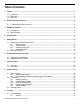
Table of Contents 1. Legend ............................................................................................................................................................................. 9 1.1. Front Panel .............................................................................................................................................................. 9 1.2. Rear Panel ..................................................................................................................
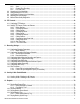
9.2. 9.3. 9.4. 9.5. 9.6. 9.1.2. View ........................................................................................................................................................ 35 9.1.3. Channel-Zero Encoding .......................................................................................................................... 35 9.1.4. Live View Icons .......................................................................................................................................
13.6. Playing Back by Sub-Periods ................................................................................................................................ 78 13.7. Playing Back External Files ................................................................................................................................... 79 13.8. Auxiliary Playback Functions ................................................................................................................................. 79 13.8.1.
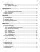
17.6.1. Checking HDD Status in HDD Information Interface............................................................................. 120 17.6.2. Checking HDD Status in System Information Interface ........................................................................ 120 17.7. Checking S.M.A.R.T. Information ........................................................................................................................ 121 17.8. Detecting Bad Sectors ..............................................
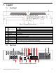
1. Legend 1.1. Front Panel Figure 1, DS-90xxHUHI-F8/N Front Panel No. Item 1. Status Indicators 2. 3. 4. 5. 6. 7. 8. IR Sensor Front Panel Lock DVD Bay Number Buttons USB Ports Function Buttons Direction Buttons 9. Enter 10. 11. Scroll Wheel On/Off Power 1.2.
Figure 3, DS-9016HUHI-F8/N Rear Panel No.
1.3.
2. IR Remote Control Operations The DVR may also be controlled with the included IR remote control. The keys on the remote control closely resemble the ones found on the front panel. NOTE: Batteries (2 × AAA) must be installed before operation. Table 1.1 , Description of the IR Remote Control Buttons No. Name 1 2 3 4 5 6 7 8 9 10 2.1.
2. Check and remember the DVR No. (default is 255). This number is valid for all IR remote controls. 3. Press the DEV button on the remote control. 4. Enter the DVR No. noted in step 2. 5. Press the ENTER button on the remote. If the Status indicator on the front panel turns blue, the remote control is operating properly. If the Status indicator does not turn blue and there is still no response from the remote, check the following: 1.
4. Soft Keyboard The on-screen keyboard allows you to enter characters. Figure 4, Soft Keyboard Icon … Description Number Icon … Description English letter Lowercase/Uppercase Backspace Switch the keyboard Space Positioning the cursor Enter Symbols Reserved 5. Getting Started 5.1. Starting Up and Shutting Down the DVR Proper startup and shutdown procedures are crucial to extending the life of the DVR. 5.1.1.
Figure 5, Shutdown Menu 2. Select the Shutdown button. 3. Click the Yes button. 4. Turn off the rear panel power switch (16 channel only) when the “Please Power Off” prompt appears. Figure 6, Shutdown Prompt 5.1.4. Rebooting the DVR While in the Shutdown menu, you can also reboot the DVR. 1. Enter the Shutdown menu by clicking Menu > Shutdown. 2. Click the Logout button to log out, or the Reboot button to reboot, the DVR. 5.2.
STRONG PASSWORD RECOMMENDED – We highly recommend you create a strong password of your own choosing (using a minimum of 8 characters, including at least three of the following categories: upper case letters, lower case letters, numbers, and special characters.) in order to increase the security of your product. We also recommend that you reset your password regularly. Especially in a high security system, resetting the password monthly or weekly can better protect your product. 2.
2) Click the Yes button to export the GUID password recovery key. The Reset Password interface pops up. 3) Navigate to the USB flash disk. 4) Click the New Folder button to create a folder on the USB flash disk. If saving the GUID from multiple machines, create a name for the folder that identifies the machine (e.g., “Jones Home, PO3243…”). 5) Double click on the new folder to switch to that location for saving. 6) Click the Export button to export the GUID file to the USB flash disk.
6. Using the Unlock Pattern for Login Configure the unlock pattern for device login by the admin. 6.1. Configuring the Unlock Pattern After the device is activated, you can enter the following interface to configure the device unlock pattern. Figure 11, Set Unlock Pattern 1. Use the mouse to draw a pattern among the nine dots on the screen. Release the mouse when the pattern is done. Figure 12, Draw the Pattern NOTE: Connect at least four dots to draw the pattern. Each dot can be connected once only.
Figure 13, Confirm the Pattern NOTE: If the two patterns are different, you must set the pattern again. Figure 14, Reset the Pattern 6.2. Logging in via Unlock Pattern NOTE: Only the admin user has permission to unlock the device. Configure the pattern before unlocking. 1. Right click the mouse on the screen and select the menu to enter the interface.
2. Draw the pre-defined pattern to unlock to enter the menu operation. NOTE: Right click the mouse to log in via the normal mode. If you have forgotten your pattern, select the Forget My Pattern or Switch User option to enter the normal login dialog box. If the pattern you draw is different from the pattern you have configured, try again. If you have drawn the wrong pattern seven times, the account will be locked for one minute. Figure 16, Normal Login Dialog Box 7. Login and Logout 7.1.
In the Login interface, for the admin, if you have entered the wrong password seven times, the account will be locked for 60 seconds. For an operator, if you have entered the wrong password five times, the account will be locked for 60 seconds. Figure 18, User Account Protection for the Admin Figure 19, User Account Protection for the Operator 4. (Optional) If you forget the password, click Forget Password to pop up the Import GUID interface. Figure 20, Import GUID File 5.
Figure 21, Reset Password 6. Input the new password and confirm the password. 7. Click OK to save the new password. Then the Attention box pops up as shown below. Figure 22, GUID File Imported 8. Click the OK button, and the Attention box pops up to remind you to duplicate the password of the device to IP cameras that are connected with default protocol. Click Yes to duplicate the password or No to cancel it.
7.2. User Logout After logging out, the monitor turns to live view mode, and if you want to perform some operations, you will need to enter the user name and password to log in again. 1. Enter the Shutdown menu, Menu > Shutdown. Figure 24, Logout 2. Click Logout. NOTE: After you have logged out of the system, menu operations on the screen are invalid. Input a user name and password to unlock the system. 8. Adding Cameras 8.1. Analog Cameras 8.1.1.
Figure 25, Add Analog Cameras Window 8.2. IP Cameras 8.2.1. Adding IP Cameras NOTE: DS-73xxHUHI-F4/N DVRs support IP cameras up to 8 MP. 1. Go to MENU > CAMERAS > IP CAMERA (TAB). 2. Press the REFRESH button to update the camera list: - Cameras listed in yellow are cameras that have been detected on the network, but not added to view on the DVR. - Cameras listed in white are cameras that have been added to view on the DVR.
Figure 26, Cameras Setup: IP Camera icon next to an active (yellow highlighted) - To add a camera(s) to the DVR: Click the camera to add a single camera to the DVR - Click the One-Touch Adding button to add all active (yellow highlighted) cameras to the DVR - The DVR will check the IP camera’s password against its own password: - If the IP Camera’s and DVR’s Passwords Match — Camera name will turn white and the camera will be added to the DVR.
8.2.2. Custom Adding IP Camera If the camera you want to add does not appear on the list, add the camera as follows: 1. Press the CUSTOM ADDING button to add the camera manually. 2. In the Add IP Camera (Custom) window, enter the following information: - IP Camera Address - Protocol - Management Port - User Name - Admin Password 3. Press Add button. Figure 27, Add IP Camera (Custom) Window 8.2.3. Modify IP Camera Settings 1. Go to MENU > CAMERAS > IP CAMERA. 2.
IP Camera Management Icons Icon Explanation EDIT (Pen): Press to edit basic IP camera parameters (must be in LAN2 range) DISCONNECTED (!): Camera is disconnected; click the icon to get camera’s exception information PLAY (Right Triangle): Play connected camera’s live video UPGRADE (Up Arrow): Upgrade the connected camera’s firmware REPAIR (?): Press to attempt to repair thE connection Icon Explanation ADD (+): Press to add the detected IP camera DELETE (Trash Can): Press to delete the camera ADVANCED (Ge
- IP Camera No. (Read Only) — Displays the camera number - IP Camera Address — Enter the camera IP address - Management Port — Enter the camera management port (default = 8000) 3. Click the Password tab to display the Password window. Figure 29, Advanced Settings: Password 4. Enter current password in Current Password field. 5. Enter new password in New Password field. 6. Re-type new password in Confirm field. 7. Click on the Apply button to validate the new password 8.
Figure 30, Cameras Setup > IP Camera Screen Figure 31, Edit IP Camera 8.3. Activating Camera A camera must be activated before first use. To activate a camera before adding it to the DVR: 1. View the status of the camera in the Camera List “Security” column.
Press One Touch Activate button. 2. • Activation message will appear on the screen prompting user to activate the device (Figure 32). • Username field will be greyed-out with the username set to “admin.” 3. Type a password of your choosing (see “Password Strength Levels” table for guidelines). 4. • The password strength will be displayed, accompanied by a color indicator. • Activation will not be allowed unless password is of acceptable strength.
Figure 34, Invalid Password Message Figure 35, Level 1 Password Strength Figure 36, Level 2 Password Strength UM DS-90xxHUHI-F8/N User Manual 041717NA 31
Figure 37, Level 3 and Level 4 Password Strength 5. After an acceptable password has been created, a confirmation message will appear (Figure 38). 6. Press the OK button to proceed.
Password Strength Levels STRENGTH LEVEL DESCRIPTION Level 0 (Risky) DVRs will not accept a Level 0 password Password length is fewer than eight characters, contains only one type of character, is the same as the user name, and/or is the mirror writing of the user name. This type of password will not be accepted. Level 1 (Weak) DVRs will accept a Level 1 password Password contains two kinds of characters.
9. Live View Live View shows the video image from each camera in real time. The DVR will automatically enter Live View mode when powered on. It is also at the very top of the menu hierarchy, thus hitting the ESC key multiple times (depending on which menu you’re on) will take you back to Live View mode. 9.1. Live View Settings 9.1.1. General Figure 39, Live View Settings 1. Go to MENU > SYSTEM CONFIGURATION > LIVE VIEW > GENERAL. 2.
9.1.2. View This section explains how to assign cameras to Live View screen positions. Figure 40, Live View View Settings 1. Go to MENU > SYSTEM CONFIGURATION > LIVE VIEW > VIEW. 2. Use pull-down menu to select the Video Output Interface you want to configure. 3. Click on a screen layout (directly beneath screen positions) that you want the monitor to have. 4. Highlight a screen position on the top right section of the screen. 5.
Figure 41, Channel-Zero Encoding 9.1.4. Live View Icons In live view mode, there are icons at the right top of the screen for each channel, showing the status of the record and alarm in the channel, so that you can know whether the channel is recorded, or whether there are alarms as soon as possible. Icons 9.2.
• Aux/Main Monitor: the DVR checks the connection of the output interfaces to define the main and auxiliary output interfaces. When the aux output is enabled, the main output cannot do any operation, and you can do some basic operation on the live view mode for the Aux output. The VGA/HDMI output is the main output. The priority relationship is shown in the following table: S.
9.4. Quick Setting Toolbar in Live View Mode On each channel’s screen, there is a quick setting toolbar that shows when you click the screen. Figure 43, Quick Setting Toolbar Icons Description Start/Stop Manual Recording Icons Description Icons Description Instant Playback Audio On/Mute PTZ Control Digital Zoom Image Settings Close Live View Face Detection Information Capture Live View Strategy Information Fisheye • Instant Playback shows only the record in last five minutes.
Figure 45, Image Settings • Face Detection can be enabled on supported cameras if you click the icon. The dialog pops up. Click Yes and the full-screen live view of the channel is enabled. You can click exit from the full-screen mode. to Figure 46, Enable Face Detection NOTE: • You can configure face detection only when it is supportsed by the connected camera.
Figure 49, Live View – General (2) The settings available in this menu include: • Video Output Interface: Selects the output (HDMI, VGA, or 4K) to configure the settings to the video output interface. NOTE: Using 4K video output disables VGA output. • Live View Mode: Selects the display mode to be used for Live View. • Dwell Time: The time in seconds to dwell between switching of channels when enabling auto-switch in Live View.
10. Click a window to select it, and then double-click a camera name in the camera list you would like to display. Setting an ‘X’ means the window will not display any camera. 11. You can also click to start live view of all channels in order and click channels. Click or to go to the previous or next page. to stop live view of all 12. Click the Apply button. 9.6.
10. PTZ Controls 10.1. Configuring PTZ Settings Follow the procedure to set the parameters for PTZ. The configuring of the PTZ parameters should be done before you control the PTZ camera. 1. Enter the PTZ Settings interface, Menu > Camera > PTZ. Figure 53, PTZ Settings 2. Select the camera for PTZ setting in the Camera drop-down list. 3. Click the PTZ Parameters button to set the PTZ parameters.
4. Select the parameters of the PTZ camera from the drop-down list. NOTE: All the parameters should be exactly the same as the PTZ camera parameters. For a connected Coaxitron camera/dome, select the HIKVISION-C PTZ protocol. Make sure the protocol selected here is supported by the connected camera/dome. If HIKVISION-C protocol is selected, all other parameters such as baud rate, data bit, stop bit, parity, and flow control are not configurable. 5.
Figure 56, PTZ Settings 2. Use the directional button to point the camera to the location where you want to set the preset; the zoom and focus operations can be recorded in the preset as well. 3. Enter the preset No. (1 to 255) in the preset text field, and click the Set button to link the location to the preset. 4. Repeat steps 2 and 3 to save more presets.
Figure 57, PTZ Panel, General 4. Click to enter the preset No. in the corresponding text field. 5. Click the Call Preset button to call it. NOTE: When a Coaxitron camera/dome is connected and the PTZ protocol is selected to HIKVISION-C, call the preset 95 to enter the menu of the connected Coaxitron camera/dome. Use the directional buttons on the PTZ control panel to operate the menu. 10.2.4.
3. Click the Set button to add key points for the patrol. Figure 59, Key Point Configuration 4. Configure key point parameters such as the key point No., duration of staying for one key point, and speed of patrol. NOTE: The key point corresponds to the preset. The Key Point No. determines the order the PTZ will follow while cycling through the patrol. Duration refers to the time to stay at the corresponding key point. Speed defines the speed at which the PTZ will move from one key point to the next. 5.
4. You can click the Stop Patrol button to stop calling it. 10.2.6. Customizing Patterns Patterns can be set by recording the movement of the PTZ. You can call the pattern to move the PTZ according to the predefined path. 1. Enter the PTZ Settings interface, Menu > Camera > PTZ. Figure 61, PTZ Settings 2. Choose pattern number in the drop-down list. 3. Click the Start button, and click corresponding buttons in the control panel, to move the PTZ camera. Click the Stop button to stop it.
Figure 62, PTZ Panel, General 3. Click the Call Pattern button to call it. 4. Click the Stop Pattern button to stop calling it. 10.2.8. Customizing Linear Scan Limit Enable Linear Scan to trigger the scan in the horizontal direction in the predefined range. NOTE: This function is supported by certain models. 1. Enter the PTZ Settings interface, Menu > Camera > PTZ. Figure 63, PTZ Settings 2.
10.2.9. Calling Linear Scan Follow the procedure to call the linear scan in the predefined scan range. 1. Click the button PTZ in the lower-right corner of the PTZ Settings interface, or press the PTZ button on the front panel, or click the PTZ Control icon the PTZ setting menu in live view mode. in the quick setting bar to enter 2. Click the One-Touch tab to show the one-touch function of the PTZ control. Figure 64, PTZ Panel, One-Touch 3.
Figure 65, PTZ Panel, One-Touch 3. Click the corresponding button to activate the one-touch park action: • Park (Quick Patrol): The dome starts patrol from the predefined preset 1 to preset 32 in order after the park time. Any undefined preset will be skipped. • Park (Patrol 1): The dome starts moving according to the predefined patrol 1 path after the park time. • Park (Preset 1): The dome moves to the predefined preset 1 location after the park time.
Figure 66, PTZ Control Panel Description of the PTZ Panel Icons Icon Description Icon Description Icon Description Direction button and the auto-cycle button Zoom+, Focus+, Iris+ Zoom-, Focus-, Iris- The speed of the PTZ movement Light on/off Wiper on/off 3D-Zoom Image Centralization Menu Switch to the PTZ control interface Switch to the one-touch control interface Switch to the general settings interface Exit Minimize windows UM DS-90xxHUHI-F8/N User Manual 041717NA 51
11. Recording Settings 11.1. Configuring Encoding Parameters 11.1.1. Before Starting 1. Make sure that the HDD has been installed. If not, install an HDD and initialize it by going to Menu > HDD > General. Figure 67, HDD, General 2. Click the Advanced tab and select HDD storage mode (Menu > HDD > Advanced > Storage Mode). • If the HDD mode is Quota, set the maximum record capacity. • If the HDD mode is Group, set the HDD group. Figure 68, HDD, Advanced 3.
Figure 69, Record Parameters 4. Set the parameters for recording. A). Select the Record tab to configure. B). Select a camera from the camera drop-down list. C). View the Camera Resolution. NOTE: When HD-TVI input is connected, you can view the information including the input signal type, resolution, and frame rate (e.g., HD-TVI 720P25). 5. Configure the following parameters for the Main Stream (Continuous) and the Main Stream (Event): Stream Type: Set the stream type to be Video or Video & Audio. 6.
960 × 1080 (1080p Lite) resolution is available when the 1080p Lite is enabled in the Record > Advanced Settings interface. 7. Bitrate Type: Set the bitrate type to be Variable or Constant. 8. Video Quality: Set the video quality of recording, with 6 levels configurable. NOTE: The Stream Type, Resolution, Bitrate Type, and Video Quality are not configurable for the Main Stream (Event) of the IP Camera. 9. Frame Rate: Set the frame rate of recording. 10. Max.
Figure 70, More Settings of Record Parameters • Pre-record: The time you set to record before the scheduled time or event. For example, when an alarm triggered the recording at 10:00, if you set the pre-record time as 5 seconds, the camera records it at 9:59:55. • Post-record: The time you set to record after the event or the scheduled time. For example, when an alarm triggered the recording ends at 11:00, if you set the post-record time as 5 seconds, it records till 11:00:05.
Figure 71, Copy Camera Settings 18. Set encoding parameters for sub-stream. A. Select the Sub-Stream tab. Figure 72, Sub-Stream Encoding B. Select a camera in the camera drop-down list. C. Configure the parameters. D. Click Apply to save the settings. E. (Optional) If the parameters can also be used to other cameras, click Copy to copy the settings to other channels. NOTE: When a 3 MP signal input is connected, the sub-stream frame rate cannot exceed 12 fps. 19. Set parameters for capture. A.
D. Click Apply to save the settings. E. (Optional) If the parameters can also be used to other cameras, click Copy to copy the settings to other channels. NOTE: The interval is the time period between two capturing actions. You can configure all the parameters on this menu on your demand. 11.2. Configuring Recording and Capture Schedule NOTE: Continuous, motion, and event triggered recording types are supported.
3. Choose the camera you want to configure in the Camera drop-down list. 4. Check the Enable Schedule checkbox. 5. Configure the record schedule. A. Click Edit. B. In the message box, you can choose the day to which you want to set schedule. C. To schedule an all-day recording, check the checkbox after the All Day item. Figure 75, Edit Schedule, All Day D. To arrange another schedule, leave the All Day checkbox blank and set the Start/End time.
Figure 77, Copy Schedule to Other Days NOTE: The Holiday option is available when you enable holiday schedule in Holiday settings. 6. Click OK to save setting and back to upper level menu. 11.2.2. Draw the Schedule 1. Click on the color icon to select a record type in the event list on the right-side of the interface.
Figure 79, Draw the Capture Schedule 2. Click and drag the mouse on the schedule. 3. Click on any area except the schedule table to finish and exit the drawing. 4. Repeat steps to set schedule for other channels. If the settings can also be used for other channels, click Copy, and then choose the channel you want to copy to. 5. Click Apply in the Record Schedule interface to save the settings. 11.3. Configuring Motion Detection Recording and Capture Set the motion detection parameters.
B. Check the Enable Motion Detection checkbox. C. Drag and draw the area for motion detection by mouse. If you want to set the motion detection for all the area in the field of view, click Full Screen. To clear the motion detection area, click Clear. NOTE: Areas that detect active motion turn solid red. Figure 81, Motion Detection, Mask D. Click Set to display the Motion Detection sub menu. Figure 82, Motion Detection Settings E.
Figure 83, Alarm Settings 2. Click the Alarm Input tab. Figure 84, Alarm Settings, Alarm Input 3. Select Alarm Input number and configure alarm parameters. 4. Choose N.O. (normally open) or N.C. (normally closed) for alarm type. 5. Check the Setting checkbox. 6. Click the Set button. Figure 85, Alarm Handling 7. Choose the alarm triggered recording channel. 8. Check the checkbox to select channel. 9. Click Apply to save settings.
10. Click OK to back to the upper level menu. 11. Repeat the steps to configure other alarm input parameters. 12. If the setting can also be applied to other alarm inputs, click Copy and choose the alarm input number. Figure 86, Copy Alarm Input 13. Configure the Recording Schedule. Refer to Configuring Recording and Capture Schedule and choose Alarm as the record type. 11.5.
Figure 88, Set Trigger Camera of VCA Alarm NOTE: The PTZ Linking function is available only for the VCA settings of IP cameras. 6. Enter Record Schedule Settings interface (Menu > Record > Schedule > Record Schedule), and set Event as the record type. 11.6. Configuring Manual Recording and Continous Capture Follow the steps to set parameters for the manual recording and continuous capture. Using manual recording and continuous capture, you need to manually cancel the recording.
Figure 90, Holiday Settings 3. Enable Edit Holiday schedule. 4. Click to enter the Edit interface. Figure 91, Edit Holiday Settings 5. Check the checkbox of Enable. 6. Select Mode from the drop-down list. NOTE: There are three holiday schedule date formats: By Month, By Week, and By Date are selectable. 7. Set the start and end date. 8. Click Apply to save settings. 9. Click OK to exit the Edit interface. 10. Configure the record schedule. Refer to Configuring Recording Schedule.
Figure 92, Edit Schedule, Holiday NOTE: Up to eight periods can be configured for each day. Time periods cannot overlap each other. In the channel timetable, both holiday schedule and normal day schedule are displayed. Repeat the above steps to set Holiday schedule for other channels. If the holiday schedule can also be used to other channels, click Copy and choose the channel you want to apply the settings. 11.8.
Figure 93, HDD Advanced B. Choose Group number in the dropdown list of Record on HDD Group C. Check the channels you want to save in this group. D. Click Apply to save settings. NOTE: After you have configured the HDD groups, configure the recording settings. 11.9. Files Protection You can lock the recorded files or set the HDD property to Read-only to protect the record files from being overwritten. 11.9.1. Protect File by Locking the Record Files 1. Enter the Export Settings interface, Menu > Export.
Figure 95, Export, Search Result 5. Find the record files you want to protect, and then click the indicating that the file is locked. , Record files of which the recording is not completed cannot be locked. NOTE: 6. Click icon which will turn to to change it to to unlock the file and the file is not protected. 11.9.2. Protect File by Setting HDD Property to Read-Only 1. Enter the HDD setting interface, Menu> HDD. 2. Set the HDD storage mode to Group. Figure 96, HDD General 3.
NOTE: You cannot save files to a Read-Only HDD. To save files to the HDD, change property to R/W. If there is only one HDD and it is set to Read-Only, the DVR cannot record any files. Only Live View mode is available. If you set the HDD to Read-Only when the DVR is saving files to it, the file will be saved in the next R/W HDD. If there is only one HDD, the recording will be stopped. 12. One-Key H.264+ Enable/Disable 12.1. One-Key H.264+ Enabling for All Cameras 1. Enter the Record menu, Menu > Record. 2.
Figure 101, Advanced Settings 3. Click Disable to disable H.264+ for all the analog cameras and the following attention box pops up. Figure 102, Attention Box 4. Click Yes to enable the function and reboot the device to have new settings taken effect. NOTE: If H.264+ is already disabled for all analog cameras, when you click the Disable button, the following attention box pops up to remind you that H.264+ is already disabled. Figure 103, Attention Box 13. Playback 13.1. Playing Back Record Files 13.1.1.
Figure 104, Instant Playback Interface Figure 105, Right-Click Menu Under Live View 13.1.2. Play Back by Time Play back video files recorded in specified time duration. Multi-channel simultaneous playback and channel switch are supportsed. 1. Enter Playback interface, Menu > Playback. 2. Check the checkbox of channel(s) in the channel list, then double-click to select a date on the calendar.
Figure 106, Playback Calendar NOTE: If there are record files for that camera in that day, in the calendar, the icon for that day is displayed as . Otherwise it is displayed as . 13.2. Playback Interface You can select the main stream or sub stream from the drop-down list for playback. You can also use the toolbar in the bottom part of Playback interface to control playing progress, as shown in the following figure. Figure 107, Playback Interface 1.
Button / / Operation Audio on/Mute Button / Operation Start/Stop clipping Add default tag Add customized tag Reverse play/Pause 30s forward Fast forward Full Screen Save the clips Stop 30s reverse Previous day Exit Process bar The end time of the files.
NOTE: Click Back button to return to the search interface. If there is only one channel triggered, clicking Full-screen Playback interface of this channel. button takes you to If several channels are triggered, clicking button takes you to the Synchronous Playback interface. Check checkbox to select one channel for playback or select multiple channels for synchronous playback. The maximum number of channels for synchronous playback varies by model. Figure 110, Select Channels for Synchronous Playback 6.
• Pre-play: The time set to play back before the event. For example, if an alarm triggers the recording at 10:00, if the pre-play time is set to 5 seconds, the video will play back from 9:59:55. • Post-play: The time to play back after the event. For example, if an alarm triggers the recording to end at 11:00, if the post-play time is set as 5 seconds, the video will play back till 11:00:05. 8. Click the or button to select the previous or next event. 13.4.
5. Tag management. Click button to check, edit, and delete tag(s). Figure 114, Tag Management Interface 6. Select Tag from the drop-down list in the Playback interface. 7. Choose channels, edit start time and end time, and then click Search to enter Search Result interface. Enter keyword in the textbox your command. NOTE: to search the tag on Figure 115, Video Search by Tag 8. Click button to play back the file. 9. Click the Back button to return to the search interface.
13.5. Playing Back by System Logs Play back record file(s) associated with channels after searching system logs. 1. Enter Log Information interface, Menu > Maintenance > Log Information. Figure 116, System Log Search Interface 2. Click Log Search tab to enter System Log Search interface. 3. Set search time and type and click Search button. Figure 117, Result of System Log Search 4. Choose a log with record file and click NOTE: UM DS-90xxHUHI-F8/N User Manual 041717NA button to enter Playback interface.
5. Playback management. The toolbar in the bottom of the Playback interface can be used to control the playing process. Figure 118, Interface of Playback by Log 13.6. Playing Back by Sub-Periods The video files can be played in multiple sub-periods simultaneously on the screens. 1. Enter Playback interface, Menu > Playback. 2. Select Sub-periods from the drop-down list in the upper-left corner of the page to enter the Sub-periods Playback interface. 3. Select a date and start playing the video file. 4.
13.7. Playing Back External Files Perform the following steps to look up and play back files in the external devices. 1. Enter the Playback interface, Menu > Playback. 2. Select the External File in the drop-down list on the top-left side. The files are listed in the right-side list. 3. You can click the button to refresh the file list. 4. Select and click the button to play back it. Figure 120, Interface of External File Playback 13.8. Auxiliary Playback Functions 13.8.1.
Figure 121, Draw Area for Digital Zoom 3. Right-click the image to exit the digital zoom interface. 13.8.3. Reverse Playback of Multi-Channels You can play back record files of multi-channel reversely. Up to 16 channels of simultaneous reverse playback is supported. 1. Enter the Playback interface, Menu > Playback. 2. Check more than one checkboxes to select multiple channels and click to select a date on the calendar. Figure 122, 4-ch Synchronous Playback Interface 3.
14. Backing Up Record Files 14.1. Before Starting Insert the backup device(s) into the device. 14.2. Backing Up by Normal Video/Picture Search Record files can be backed up to various devices such as USB devices (USB flash drives, USB HDDs, USB writer), SATA writer, and e-SATA HDD. 14.2.1. Back Up Using USB Flash Drives and USB HDDs 1. Enter Export interface, Menu > Export > Normal/Picture. 2. Select the cameras to search. 3. Select Main/Sub Stream and Recording Mode.
Figure 124, Result of Normal Video Search for Backup 7. Select video files from the Chart or List to export, and click the button Export to enter the Export interface. NOTE: You can also click Export All to select all the video files for backup and enter the Export interface. Figure 125, Export by Normal Video Search Using USB Flash Drive 8. Select the backup device from the drop-down list (you can also select the file format to filter the files existing in the backup device). 9. Select the saving type.
Figure 126, Select File or Player for Backup 11. A prompt message will pop up after the backup process is complete. Click OK to confirm. Figure 127, Export Finished 14.3. Backing Up by Event Search Back up event-related record files using USB devices (USB flash drives, USB HDDs, USB writer), SATA writer, or eSATA HDD. Quick Backup and Normal Backup are supported. 1. Enter Export interface, Menu > Export > Event. 2. Select the cameras to search. 3. Select the event type to alarm input, motion, or VCA.
Figure 129, Result of Event Search 6. Export the video files. 14.4. Backing Up Video Clips You may select video clips in playback mode to export directly during Playback, using USB devices (USB flash drives, USB HDDs, USB writer), or SATA writer. 1. Enter Playback interface. 2. During playback, use the file(s). 3. Click or buttons in the playback toolbar to start or stop clipping record to enter the file management interface. Figure 130, Video Clips Export Interface 4.
1. Enter the Export interface, Backup Device Management. Figure 131, Storage Device Management 2. Click New Folder button if you want to create a new folder in the backup device. 3. Select a record file or folder in the backup device and click the button if you want to delete it. 4. Click Erase button if you want to erase the files from a re-writable CD/DVD. 5. Click Format button to format the backup device.
3. Set detection area and sensitivity. 4. Check motion detection checkbox. 5. Use the mouse to draw detection area(s) or click Full Screen to set the area to be the full screen. 6. Drag the sensitivity bar to set sensitivity. 7. Click to set alarm response actions. Figure 133, Set Detection Area and Sensitivity 8. Click Trigger Channel tab and select one or more channels that will start to record or become full-screen monitoring when a motion alarm is triggered.
Figure 135, Set Arming Schedule of Motion Detection 11. Click Linkage Action tab to set up alarm response actions of motion alarm. 12. Repeat the above steps to set up arming schedule for other days of the week. 13. Click the OK button to complete the channel’s motion detection settings. 14. To set motion detection for another channel, repeat the above steps or just copy above settings to it. NOTE: You are not allowed to copy the “Trigger Channel” action. 15.2.
5. Select Trigger Channel tab and select one or more channels that will start to record or become full-screen monitoring when an external alarm input is triggered. 6. Select Arming Schedule tab to set the channel’s arming schedule. 7. Choose one day of a week, a maximum of eight time periods can be set within each day. Time periods must not repeat or overlap. NOTE: Figure 137, Set Arming Schedule of Alarm Input 8. Select Linkage Action tab to set up alarm response actions of the alarm input. 9.
Figure 138, Set PTZ Linking of Alarm Input 12. To set handling action of another alarm input, repeat the above steps or just copy above settings to it. Figure 139, Copy Settings of Alarm Input 15.3. Detecting Video Loss Detect video loss of a channel and take alarm response action(s). 1. Enter Camera Management Video Loss interface, Menu > Camera > Video Loss. 2. Select a channel you want to detect.
Figure 140, Video Loss Setup Interface 3. Set up handling method for a video loss. 4. Check the Enable Video Loss Alarm checkbox. 5. Click the Set button to set up handling method of video loss. 6. Set arming schedule of the channel. 7. Select Arming Schedule tab to set the channel’s arming schedule. 8. Choose one day of a week and up to eight time periods can be set within each day. Or you can click the Copy button to copy the time period settings to other day(s). Time periods must not repeat or overlap.
15.4. Detecting Video Tampering Trigger alarm when the lens is covered and take alarm response action(s). 1. Enter Camera Management Video Tampering interface, Menu > Camera > Video Tampering Detection. 2. Select a channel on which you want to detect video tampering. Figure 142, Video Tampering Interface 3. Check the Enable Video Tampering Detection checkbox. 4. Drag the sensitivity bar to choose sensitivity level. 5. Click Set button to set video tampering handling method.
9. Repeat the above steps to set arming schedule for other days of the week. You can also use the Copy button to copy an arming schedule to other days. 10. Click the OK button to complete the video tampering settings of the channel. 11. Repeat the above steps to set other channels, or click the Copy button copy the settings to them. 12. Click the Apply button to save and activate the settings. 15.5. Setting All-Day Video Quality Diagnostics Video quality can be diagnosed manually and all-day.
Figure 145, Set Arming Schedule of Video Quality Diagnostics 9. Select Linkage Action tab to set alarm response actions of video quality diagnostics alarm. 10. Repeat the above steps to set arming schedule for other days of the week. You can also use the Copy button to copy an arming schedule to other days. 11. Click the OK button to complete the channel’s video quality diagnostics settings. 12. Click the Apply button to save and activate settings. 13.
Figure 146, Exception Settings Interface 3. Check the Enable Event Hint checkbox to display the (Event/Exception icon) when an exceptional event occurs. Click the Set Button to display the detailed event hint. Figure 147, Event Hint Settings NOTE: UM DS-90xxHUHI-F8/N User Manual 041717NA Click the icon in the Live View interface to view detailed information of the exceptional event. Click the Set button to display the detailed event hint.
Figure 148, Detailed Event 4. Set the alarm linkage actions. 5. Click Apply to save the settings. 15.7. Setting Alarm Response Actions Alarm response actions will be activated when an alarm or exception occurs, including Full Screen Monitoring, Audible Warning (buzzer), Notify Surveillance Center, Send E-mail, and Trigger Alarm Output.
Figure 149, Alarm Output Settings Interface If Manually Clear is selected in the Dwell Time drop-down list, clear it by going to Menu > Record Configuration > Trigger. NOTE: 3. Click the Set button to set the alarm output arming schedule. 4. Choose one day of a week, and up to eight time periods can be set within each day. Time periods must not repeat or overlap. NOTE: Figure 150, Set Arming Schedule of Alarm Output 5. Repeat the above steps to set arming schedule for other days of a week.
Figure 151, Network Settings Interface NOTE: One self-adaptive network interface is provided. 2. Select the General tab. 3. Configure the following parameters: NIC Type, IPv4 Address, IPv4 Gateway, MTU, DNS Server, and Main NIC. NOTE: The valid MTU value is from 500 to 1500. If a DHCP server is available, check the Enable DHCP checkbox to obtain an IP address and other network settings automatically from that server.
3. Check the Enable PPPoE checkbox to enable this feature. 4. Enter User Name and Password for PPPoE access. NOTE: The User Name and Password is assigned by your ISP. 5. Click the Apply button to save the settings. 6. After successful settings, the system asks you to reboot the device to enable the new settings, and the PPPoE dial-up is automatically connected after the reboot. 7. Go to Menu > Maintenance > System Info > Network interface to view the PPPoE connection status. 16.2.2.
16.2.3. Enable Hik-Connect P2P on the NVR. 1. Go to Main Menu > System Configuration > Network > Platform Access. 2. Check the Enable checkbox. 3. Server Address must be “dev.hik-connect.com.” If not, check the Custom checkbox, and type “dev.hik-connect.com.” 4. To turn Enable Stream Encryption on, select its checkbox. 5. Click the Apply button. Status will change to “Online” (if all settings are correct). 6.
encrypted verification code is empty and the configuration file’s verification code is “ABCDEF.” Under either of these conditions, create a new verification code or delete the default code and input the same same default verification code. 16.2.5. Accessing the NVR After configuration, you can access and manage the NVR on your mobile phone with the HIK-Connect Cloud P2P app (iOS or Android) or through the HIK-Connect website (www.hik-connect.com).
NOTE: The time synchronization interval can be set from 1 to 10080 minutes. The default value is 60 minutes. If the DVR is connected to a public network, use an NTP server that has a time synchronization function such as the server at the National Time Center (IP Address: 210.72.145.44). If the DVR is set in a customized network, NTP software can be used to establish an NTP server used for time synchronization. 16.2.7.
2) Click the Refresh button to get the latest status of the port mapping. - OPTION 2: Manual 1) If you select Manual as the mapping type, you can edit the external port on demand by clicking to activate the External Port Settings dialog box. 2) Click to activate the External Port Settings dialog box. Configure the external port No. for server port, http port, and RTSP port respectively. You can use the default port No., or change it according to actual requirements.
Figure 158, More Settings Interface 3. Configure the remote alarm host, server port, HTTP port, multicast, and RTSP port. • Alarm Host IP/Port: With a remote alarm host configured, the device will send the alarm event or exception message to the host when an alarm is triggered. The remote alarm host must have the CMS (Client Management System) software installed. The Alarm Host IP refers to the IP address of the remote PC on which the CMS (Client Management System) software (e.g.
NOTE: The Server Port should be set in the range of 2000-65535 and is used for remote client software access. The HTTP port is used for remote IE access. • Output Bandwidth Limit: You can check the checkbox to enable output bandwidth limit. • Output Bandwidth: After enabling the output bandwidth limit, input the output bandwidth in the text field. NOTE: The output bandwidth limit is used for remote Live View and playback. The minimum output bandwidth is 2 Mbps. 4.
Figure 160, Create Self-signed Certificate 2) Enter the country, host name/IP, validity, and other information. 3) Click OK to save the settings. • OPTION 2: Create the authorized certificate. 1) Click the Create button to create the certificate request. 2) Download the certificate request and submit it to the trusted certificate authority for signature. 3) After receiving the signed valid certificate, import the certificate to the device.
Figure 162, E-mail Settings Interface 3. Configure the following e-mail settings: • Enable Server Authentication (optional): Check the checkbox to enable the server authentication feature. • User Name: The user account of sender’s e-mail for SMTP server authentication. • Password: The password of sender’s e-mail for SMTP server authentication. • SMTP Server: The SMTP Server IP address or host name (e.g., smtp.263xmail.com). • SMTP Port: The SMTP port. The default TCP/IP port used for SMTP is 25.
NOTE: Three attached pictures can be sent for one analog camera when the alarm is triggered. • Interval: Refers to the time between two actions of sending attached pictures. • E-mail Test: Sends a test message to verify the SMTP server can be reached. 4. Click the Apply button to save the e-mail settings. 5. Click the Test button to test whether your E-mail settings work. The corresponding Attention message box pops up. Figure 163, E-Mail Testing Attention 16.2.11.
Figure 165, Network Detection Interface 3. Select a NIC to test network delay and packet loss. 4. Enter the destination address in the Destination Address text field. 5. Click the Test button to start testing network delay and packet loss. 16.3.2. Exporting Network Packet By connecting the DVR to a network, the captured network data packet can be exported to a USB flash disk, SATA, and other local backup devices. 1. Enter the Network Traffic interface, Menu > Maintenance > Net Detect. 2.
4. Click the Export button to start exporting. 5. After the export is complete, click OK to finish the packet export. Figure 167, Packet Export Attention Up to 1 MB of data can be exported each time. NOTE: 16.3.3. Checking Network Status You can also check the network status and quick set the network parameters in this interface. 1. Enter the Network Traffic interface, Menu > Maintenance > Net Detect. 2. Click the Network Detection tab to enter the Network Detection interface. 3.
Figure 170, Network Parameters Configuration 16.3.4. Checking Network Statistics You can check the network statistics to obtain the real-time information of the device. 1. Enter the Network Statistics interface, Menu > Maintenance> Net Detect. 2. Click the Network Stat. tab to enter the Network Statistics interface. Figure 171, Network Stat. Interface 3. View the Remote Live View bandwidth, Remote Playback bandwidth, and Net Total Idle bandwidth. 4.
17. HDD Management 17.1. Initializing HDDs A newly installed hard disk drive (HDD) must be initialized before it can be used with the DVR. NOTE: Systems with HDDs installed at the factory come pre-initialized. 1. Enter the HDD Information interface, Menu > HDD > General. Figure 172, HDD Information Interface 2. View HDD’s Total Capacity, Free Space, and Remaining Recording Time (this uses the average bit rate for the channel, allowing smart encoding to increase accuracy). 3.
6. After the HDD has been initialized, the status of the HDD will change from Uninitialized to Normal. Figure 175, HDD Status Changes to Normal NOTE: Initializing the HDD will erase all data on it. HDDs that are free from working for a long period of time can be put to sleep to decrease the power consumption of the device and extend its life. 7. Click Menu > HDD > Advanced. Figure 176, Enable HDD Sleeping 8.
Figure 178, NetHDD Information Interface 3. Add the allocated NetHDD. 4. Select type as NAS or IP SAN. 5. Configure the NAS or IP SAN settings. Adding a NAS Disk 1) Enter the NetHDD IP address in the text field. 2) Click Search to search the available NAS disks. 3) Select a NAS disk from the list or manually enter the directory in the NetHDD Directory text field. 4) Click OK to add the configured NAS disk. NOTE: Up to eight NAS disks can be added.
3) Select the IP SAN disk from the list shown. 4) Click the OK button to add the selected IP SAN disk. NOTE: Up to eight IP SAN disks can be added. Figure 180, Add IP SAN Disk 6. After having successfully added the NAS or IP SAN disk, return to the HDD Information menu. The added NetHDD will be displayed in the list. NOTE: If the added NetHDD is uninitialized, select it and click the Init button for initialization. Figure 181, Initialize Added NetHDD 17.3. Managing HDD Groups 17.3.1.
Figure 182, Storage Mode Interface 3. Click the Apply button and the following Attention box will pop up. Figure 183, Attention for Reboot 4. Click the Yes button to reboot the device and activate the changes. 5. After reboot of device, enter the HDD Information interface, Menu > HDD > General. 6. Select HDD from the list and click the icon to enter the Local HDD Settings interface.
7. Select the Group number for the current HDD. NOTE: The default group No. for each HDD is 1. 8. Click the OK button to confirm the settings. Figure 185, Confirm HDD Group Settings 9. In the pop-up Attention box, click the Yes button to finish the settings. 17.3.2. Setting HDD Property The HDD property can be set to redundancy, read-only, or read/write (R/W). Before setting the HDD property, set the storage mode to Group.
17.4. Configuring Quota Mode Each camera can be configured with allocated quota for the storage of recorded files. 1. Enter the Storage Mode interface, Menu > HDD > Advanced. 2. Click the Storage Mode tab. 3. Set the Mode to Quota. 4. Reboot the DVR to enable the changes to take effect. Figure 187, Storage Mode Settings Interface 5. Select a camera for which you want to configure quota. 6. Enter the storage capacity in the Max. Record Capacity (GB) text field. 7.
10. Click the Apply button to apply the settings. NOTE: If the quota capacity is set to 0, then all cameras will use the total capacity of the HDD to record. 17.5. Configuring Cloud Storage Cloud storage allows uploading and downloading of recorded files anytime and anyplace. 1. Enter the Cloud Storage interface, Menu > HDD > General > Cloud Storage. 2. Check the Enable Cloud checkbox to enable the feature. 3. Select the One Drive, Google Drive, or Dropbox Cloud Type from the drop-down list.
Figure 190, Record Schedule 8. Upload the event triggered recording files to the cloud storage. 9. Enter the cloud storage interface and select the camera you have set in the recording schedule interface. 10. Select the upload type (default is Record) in the Upload Type text filed. 11. Check the Enable Event Upload checkbox. 12. Click Apply to finish the settings.
Configure the event triggered recording schedule and enable the corresponding event type. 13. (Optional) Click the Copy button to copy the cloud storage settings to other cameras. You can also click the Analog/IP Camera checkbox to select all cameras. 14. Click OK button to go back to the cloud storage interface. 15. Click Apply to finish the settings. Figure 192, Copy to Interface 17.6.
17.7. Checking S.M.A.R.T. Information The S.M.A.R.T. (Self-Monitoring, Analysis and Reporting Technology) is a monitoring system for HDD to detect and report on various indicators of reliability in the hopes of anticipating failures. 1. Enter the HDD Detect interface, Menu > Maintenance > HDD Detect. 2. Click the S.M.A.R.T. Settings tab to enter the interface. 3. Select the HDD to view its S.M.A.R.T. information list. NOTE: To use the HDD even when S.M.A.R.T.
Figure 196, Bad Sector Detecting 4. Click the Pause button to pause the detection and click the Resume button to resume the detection. 5. If there is error information about the HDD, click the Error Info button to view the information. 17.9. Configuring HDD Error Alarms You can configure the HDD Uninitialized or Abnormal error alarms. 1. Enter the Exception interface, Menu > Configuration > Exceptions. 2. Select the HDD Error Exception Type from the drop-down list. 3.
Figure 197, Configure HDD Error Alarm 4. When Trigger Alarm Output is selected, also select the alarm output to be triggered from the list below. 5. Click the Apply button to save the settings.
18. RAID Setup 18.1. Configuring Array RAID (redundant array of independent disks) is a storage technology that combines multiple disk drive components into a logical unit. A RAID setup stores data over multiple hard disk drives to provide enough redundancy so that data can be recovered if one disk fails. Data is distributed across the drives in one of several ways called “RAID levels,” depending on what level of redundancy and performance is required. The NVR supports software-based disk array.
18.1.3. Enable RAID Perform the following steps to enable the RAID function, or the disk array cannot be created. • OPTION 1: Enable the RAID function in the Wizard when the device starts up, refer to step 7 of Chapter 2.2. • OPTION 2: Enable the RAID function in the HDD Management Interface. 1. Enter the disk mode configuration interface, Menu > HDD > Advanced. Figure 199 Enable RAID Interface 2. Check the checkbox of Enable RAID. 3. Click the Apply button to save the settings. 18.1.4.
3. Click the One-touch Create button to enter the One-touch Array Configuration interface. Figure 201 One-Touch Array Configuration 4. Edit the array name in the Array Name text filed and click OK button to start configuring array. NOTE: If you install four HDDs or above for one-touch configuration, a hot spare disk will be set by default. It is recommended to set a hot spare disk to automatically rebuild the array when the array is abnormal. 5.
Figure 204 Physical Disk Settings Interface 2. Click Create button to enter the Create Array interface. Figure 205 Create Array Interface 3. Edit the Array Name; set the RAID Level to RAID 0, RAID 1, RAID 5, RAID 6, or RAID 10; select the Physical Disk that you want to configure array. NOTES: If you choose RAID 0, at least two HDDs must be installed. If you choose RAID 1, two HDDs need to be configured for RAID 1. If you choose RAID 5, at least three HDDs must be installed.
Figure 206 Error Message Box 5. You can click Array tab to view the successfully created array. Figure 207 Array Settings Interface 18.2. Rebuilding Array The array working status includes Functional, Degraded, and Offline. By viewing the array status, you can take immediate and proper maintenance of the disks to ensure high data security and reliability.
NOTE: Only global hot spare mode is supported. 18.2.2. Automatically Rebuilding Array When the virtual disk is in Degraded status, the device can rebuild the array automatically with the hot spare disk to ensure the high security and reliability of the data. 1. Enter the Array Settings interface, Menu > HDD > RAID > Array. The array status is Degraded.
3. Select the available physical disk and click OK button to confirm rebuilding the array. 4. When “Do not unplug the physical disk when it is under rebuilding” message appears, click OK. 5. Enter the Array Settings interface to view the rebuilding status. 6. After rebuilding is successfully, the array and virtual disk will restore to Functional. 18.3. Deleting Array NOTE: Deleting the array will delete all data in the array. 1. Enter the Array Settings interface, Menu > HDD > RAID > Array.
2. Set the Background Task Speed in the drop-down list. 3. Click the Apply button to save the settings.
19. POS Configuration 19.1. Configuring POS Settings 1. Enter the POS settings interface, Menu > Configuration > POS > POS Settings. 2. Select the POS from the drop-down list. Up to eight POS units are selectable. 3. Check the Enable checkbox to enable the POS function. Figure 1-1 POS Settings 4. Filter the POS privacy information if needed. 1) Click after Privacy Settings to enter POS Privacy Information Filtering interface.
Figure 1-2 POS Privacy Information Filtering 2) Edit the Privacy Information in the text filed to hide the input information overlay. Up to 3 pieces of privacy information can be edited and no more than 32 characters can be input for each piece of information. 3) Click OK to save the settings. 4) Select the POS protocol to Universal Protocol, EPSON, AVE, or NUCLEUS. • Universal Protocol Click the Advanced button to expand more settings when selecting the universal protocol.
2) Edit the Employee, Shift and Terminal information. No more than 32 characters can be input. 3) Click OK to save the settings. If you select NUCLEUS protocol, the connection type defaults to RS-232 and all the other POS protocol settings will change to NUCLEUS. NOTE: You should set Usage to be Transparent Channel for RS-232 settings in Menu > Configuration > RS-232 first.
Figure 1-8 USB-to-RS-232 Settings • RS-232 Connection Connect the DVR and the POS machine via RS-232. The RS-232 settings can be configured in Menu > System Configuration > RS-232. The Usage must be set to Transparent Channel. Figure 1-9 RS-232 Settings • Multicast Connection When connecting the DVR and the POS machine via Multicast protocol, set the multicast address and port. Figure 1-10 Multicast Settings • Sniff Connection Connect the DVR and the POS machine via Sniff.
Figure 1-11 Sniff Settings 5. Set other parameters of characters overly. 1) Select the character encoding format from the drop-down list. 2) Select the overlay mode of the characters to display in scrolling or page mode. 3) Select the font size to small, medium or large. 4) Set the overlay time of the characters. The value ranges from 5 to 3600 sec. 5) Set the delay time of the characters. The value ranges from 5 to 3600 sec. 6) (Optional) Check the checkbox to enable the POS Overlay in Live View.
Figure 1-13 Copy POS Settings 19.2. Configuring Overlay Channel You can assign the POS machine to corresponding channel on which you want to overlay. 1. Enter the Overlay Channel interface, Menu > Configuration > POS > Overlay Channel. 2. Click to select an analog or IP camera from the camera list on the right, and then click a POS item from the POS list you want to overlay on the selected camera. 3. Click or to go to the previous or next page of cameras.
1. Enter the POS Settings interface, Menu > Configuration > POS > POS Settings. 2. Follow the steps in Chapter 9.1-9.2 to configure the POS settings. 3. Click to enter the alarm settings interface. Figure 1-15 Set Trigger Cameras of POS 4. Click Trigger Channel tab and select one or more channels to record or become full-screen monitoring when POS alarm is triggered. 5. Set arming schedule of the channel. 1) Select Arming Schedule tab to set the channel’s arming schedule.
6. Select PTZ Linking tab and set PTZ linkage of the POS alarm. 1) Set PTZ linking parameters and click the OK button to complete the settings of the alarm input. NOTE: Check whether the PTZ or speed dome supports PTZ linkage. Figure 1-17 Set PTZ Linking 1) Click OK to save the settings.
20. Camera Settings 20.1. Configuring OSD Settings Configure the OSD (On-Screen Display) settings for the camera, including date/time, camera name, etc. 1. Enter the OSD Configuration interface, Menu > Camera > OSD. 2. Select the camera to configure OSD settings. 3. Edit the Camera Name in the text field. 4. Configure the Display Name, Display Date, and Display Week by checking the checkbox. 5. Select the Date Format, Time Format, Display Mode, and the OSD Font. Figure 215, OSD Configuration Interface 6.
9. Select the camera(s) to be configured with the same OSD settings. You can also check the Analog checkbox to select all cameras. 10. Click the OK button to finish the Copy settings and go back to the OSD Configuration interface. 11. Click the Apply button to apply the settings. 20.2. Configuring Privacy Mask You can configure four-sided privacy mask zones that cannot be viewed or recorded by the operator. 1. Enter the Privacy Mask Settings interface, Menu > Camera > Privacy Mask. 2.
20.3. Configuring Video Parameters 20.3.1. Configuring Image Settings 1. Enter the Image Settings interface, Menu > Camera > Image. 2. Select the Image Settings tab. Figure 219, Image Settings Interface (Analog Camera) Figure 220, Image Settings Interface (IP Camera) 3. Select the camera to set image parameters. 4. Two periods for different image settings are provided, select a period name in the drop-down list. NOTE: Time periods cannot overlap. 5.
7. You can click Copy to copy the image settings of the current camera to other cameras. 8. Click Apply to save the settings.
20.3.2. Configuring Camera Parameters Settings 1. Enter the Image Settings interface, Menu > Camera > Image. 2. Select the Camera Parameters Settings tab. Figure 221, Camera Parameters Settings 3. Select a camera from the drop-down list. 4. Adjust the camera parameters. The parameters include Day to Night Sensitivity, Night to Day Sensitivity, and IR Light Brightness. You can also click Default to reset the parameters to the default settings. 5.
The DVR connects to the camera via the Coaxitron protocol and there is no response mechanism. Even if the Coaxitron connection is abnormal, the parameters are still displayed to be set successfully. 21. DVR Management and Maintenance 21.1. Viewing System Information 1. Enter the System Information interface, Menu > Maintenance > System Info. 2. Click the Device Info, Camera, Record, Network, and HDD tabs to view the device’s system information.
Figure 223, Log Search Interface 2. Set the log search conditions to refine your search, including the Start Time, End Time, Major Type, and Minor Type. 3. Click the Search button to start searching log files. 4. Matching log files will be listed. NOTE: Up to 2,000 log files can be displayed each time. Figure 224, Log Search Results 5. Click the button of each log or double-click it to view its detailed information. You can also click the button to view the related video files if available.
Figure 225, Log Information Interface 6. To export the log files, click the Export button to enter the Export menu. Figure 226, Export Log Files 7. Select the backup device from the Device Name drop-down list. 8. Click the Export button to export the log files to the selected backup device. 9. Click the New Folder button to create a new folder in the backup device, or click the Format button to format the backup device before log export.
21.3. Importing/Exporting Configuration Files 21.3.1. Purpose The DVR configuration files can be exported to a local device for backup, and the configuration files of one DVR can be imported to multiple DVR devices if they are to be configured with the same parameters. 1. Enter the Import/Export Configuration File interface, Menu > Maintenance > Import/Export. Figure 227, Import/Export Configuration File 2. Click the Export button to export the configuration files to the selected local backup device. 3.
Figure 228, Local Upgrade Interface 4. Select the update file from the backup device. 5. Click the Upgrade button to start upgrading. 6. After the upgrading is complete, reboot the DVR to activate the new firmware. 21.4.2. Upgrading by FTP 1. Configure PC (running FTP server) and DVR to the same Local Area Network. Run the third-party TFTP software on the PC and copy the firmware into the TFTP root directory. 2. Enter the Upgrade interface, Menu > Maintenance > Upgrade. 3.
Figure 229, FTP Upgrade Interface 4. Enter the FTP Server Address in the text field. 5. Click the Upgrade button to start upgrading. 6. After the upgrading is complete, reboot the DVR to activate the new firmware. 21.5. Restoring Default Settings 1. Enter the Default interface, Menu > Maintenance > Default. Figure 230, Restore Defaults 2. Select the restoring type from the following three options.
3. Click the OK button to restore the default settings. NOTE: The device will reboot automatically after restoring to the default settings. 21.6. Configuring General Settings You can configure the output resolution, system time, mouse pointer speed, etc. 1. Enter the General Settings interface, Menu > Configuration > General. 2. Select the General tab. Figure 231, General Settings Interface for Simultaneous VGA and HDMI Output Figure 232, General Settings Interface for Independent VGA and HDMI Output 3.
• System Time: Select the system time. • Mouse Pointer Speed: Set the mouse pointer speed, four levels are configurable. • Enable Wizard: Enable/disable the Wizard when the device starts up. • Enable Password: Enable/disable the use of the login password. NOTE: If you check the Enable Password checkbox, everytime you log in to the DVR, the Unlock Pattern interface will pop up. If you uncheck the Enable Password checkbox, the Unlock Pattern interface will not pop up when you log in to the DVR. 4.
Figure 234, More Settings Interface (1) Figure 235, More Settings Interface (2) Figure 236, More Settings Interface (3) Figure 237, More Settings Interface (4) 3. Configure the following settings: • Device Name: Edit the DVR name. • Device No.: Edit the DVR serial number. The Device No. can be set in the range of 1 to 255 (default is 255). • Auto Logout: Set menu inactivity timeout time (e.g.
Figure 238, Enable Enhanced VCA Mode 4. If enhanced VCA mode has been enabled, you can disable it by unchecking the checkbox. When you disable it and click Apply, an attention box pops up. Click Yes to apply the function and reboot the device. Figure 239, Disable Enhanced VCA Mode 5. Click the Apply button to save the settings. 21.9. Managing User Accounts There is a default account in the DVR: Administrator.
Figure 240, User Management Interface 2. Click the Add button to enter the Add User interface. Figure 241, Add User Menu 3. Enter the information for a new user, including User Name, Password, Confirm, Level, and User’s MAC Address. 4. Password: Set the password for the user account.
STRONG PASSWORD RECOMMENDED – We highly recommend you create a strong password of your own choosing (using a minimum of 8 characters, including at least three of the following categories: upper case letters, lower case letters, numbers, and special characters) in order to increase the security of your product. We also recommend you reset your password regularly. Especially in high security systems, resetting the password monthly or weekly can better protect your product. 5.
Figure 243, User Permission Settings Interface 8. Set the user operating permission for Local Configuration, Remote Configuration, and Camera Configuration. • • • Local Configuration - Local Log Search: Searching and viewing logs and system information of device. - Local Parameters Settings: Configuring parameters, restoring factory default parameters, and importing/exporting configuration files.
21.9.2. Deleting a User 1. Enter the User Management interface, Menu > Configuration > User. 2. Select the user to be deleted from the list. Figure 244, User List 3. Click to delete the selected user account. 21.9.3. Editing a User For the added user accounts, you can edit the parameters. 1. Enter the User Management interface, Menu > Configuration > User. 2. Select the user to be edited from the list. 3. Click the icon to enter the Edit User interface. Figure 245, Edit User Interface 4.
You are allowed only to edit the password and MAC address. Check the Change Password checkbox if you want to change the password, and input the correct old password, and the new password in the Password and Confirm text fields. STRONG PASSWORD RECOMMENDED – We highly recommend you create a strong password of your own choosing (using a minimum of 8 characters, including at least three of the following categories: upper case letters, lower case letters, numbers, and special characters.
Figure 247, Export GUID File NOTE: You must input the correct old password of the admin before exporting the GUID file. 10. Click the OK button to save the settings and exit from the menu. 11. (Optional) For an Operator or Guest user account, you can also click the User Management interface to edit the permission.
22. Appendix 22.1. Glossary • Dual-Stream. A technology used to record high resolution video locally while transmitting a lower resolution stream over the network. The two streams are generated by the DVR, with the main stream having a maximum resolution of 1080p and the sub-stream having a maximum resolution of CIF. • DVR (Digital Video Recorder). A device that is able to accept video signals from analog cameras, compress the signal and store it on its hard drives. • HDD (Hard Disk Drive).
22.2. Troubleshooting • No image displayed on the monitor after the device is starting up normally. Possible Reasons: - No VGA or HDMI connections. - Connection cable is damaged. - Input mode of the monitor is incorrect. 1. Verify the device is connected to the monitor via HDMI or VGA cable. If not, connect the device to the monitor and reboot. 2. Verify the connection cable is good.
8. If the HDD is not detected or the status is Abnormal, replace the HDD according to the requirement. 9. Check if the fault is solved. 10. If it is solved, finish the process. If not, please contact Hikvision technical support. • Live View image freezes when video outputs locally. Possible Reasons: - The frame rate has not reached the real-time frame rate. 1. Check the parameters of Main Stream (Continuous) and Main Stream (Event). 2.
1. Verify the frame rate is real-time frame rate. 2. Select “Menu > Record > Parameters > Record”, and set the Frame Rate to “Full Frame”. 3. Verify the hardware supports the playback. 4. Reduce the channel number of playback. 5. Select Menu > Record > Encoding > Record, and set the resolution and bitrate to a lower level. 6. Reduce the number of local playback channels. 7. Select Menu > Playback, and uncheck the checkboxes of unnecessary channels. 8. Check if the fault is solved by the above steps. 9.
Hikvision USA Inc., 18639 Railroad Street, City of Industry, CA 91748, USA • Hikvision Canada, 4485 Dobrin, St-Laurent, Quebec, Canada, H4R 2L8 Tel: +1-909-895-0400 • Toll Free in USA: +1-866-200-6690 • E-Mail: sales.usa@hikvision.com • www.hikvision.com © 2017 Hikvision USA Inc. • All Rights Reserved • Specifications subject to change without notice.