Network Video Recorder User Manual UD07098N
Network Video Recorder User Manual User Manual About this Manual This Manual is applicable to Network Video Recorder (NVR). The Manual includes instructions for using and managing the product. Pictures, charts, images and all other information hereinafter are for description and explanation only. The information contained in the Manual is subject to change, without notice, due to firmware updates or other reasons. Please find the latest version in the company website.
Network Video Recorder User Manual Regulatory Information FCC Information Please take attention that changes or modification not expressly approved by the party responsible for compliance could void the user’s authority to operate the equipment. FCC compliance: This equipment has been tested and found to comply with the limits for a Class A digital device, pursuant to part 15 of the FCC Rules.
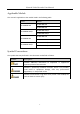
Network Video Recorder User Manual Applicable Models This manual is applicable to the models listed in the following table. Series DS-96000NI-I16 DS-96000NI-I16/H DS-96000NI-I24 DS-96000NI-I24/H Model DS-96128NI-I16 DS-96256NI-I16 DS-96128NI-I16/H DS-96256NI-I16/H DS-96128NI-I24 DS-96256NI-I24 DS-96128NI-I24/H DS-96256NI-I24/H Symbol Conventions The symbols that may be found in this document are defined as follows.
Network Video Recorder User Manual Safety Instructions Proper configuration of all passwords and other security settings is the responsibility of the installer and/or end-user. In the use of the product, you must be in strict compliance with the electrical safety regulations of the nation and region. Please refer to technical specifications for detailed information.
Network Video Recorder User Manual Product Key Features General Connectable to network cameras, network dome and encoders. Connectable to the third-party network cameras like ACTI, Arecont, AXIS, Bosch, Brickcom, Canon, PANASONIC, Pelco, SAMSUNG, SANYO, SONY, Vivotek and ZAVIO, and cameras that adopt ONVIF or PSIA protocol. Connectable to the smart IP cameras. H.265, H.264, SVAC, MPEG4, and MJPEG (only for Hikvision IP camera) video formats. PAL/NTSC adaptive video inputs.
Network Video Recorder User Manual HDD group management. Supports HDD standby function. HDD property: redundancy, read-only, read/write (R/W). HDD quota management; different capacity can be assigned to different channel. RAID 0, RAID 1, RAID 5, RAID 6, and RAID 10 are supported. Hot-swappable RAID storage scheme, and can be enabled and disabled on your demand. And 16/24 arrays can be configured. Disk clone to the eSATA disk. HDD health monitoring.
Network Video Recorder User Manual Important files search and export. Vehicle detection files and human appearance files search and export. Export video data by USB, SATA or eSATA device. Export video clips when playback. Management and maintenance of backup devices. Either Normal or Hot Spare working mode is configurable to constitute an N+1 hot spare system. Alarm and Exception Configurable arming time of alarm input/output.
Network Video Recorder User Manual ANR (Automatic Network Replenishment) function is supported, which enables the IP camera save the recording files in the local storage when the network is disconnected, and synchronizes the files to the device when the network is resumed. Remote reverse playback via RTSP. Supports accessing by the platform via ONVIF. Remote search, playback, download, locking and unlocking of the record files, and support downloading files broken transfer resume.
Network Video Recorder User Manual TABLE OF CONTENTS Chapter 1 Introduction ................................................................................................................... 16 1.1 Front Panel ....................................................................................................................... 16 1.1.1 DS-96000NI-I16(/H) Series ...................................................................................... 16 1.1.2 DS-90000NI-I24(/H) Series .......................
Network Video Recorder User Manual 4.2 Configure Privacy Mask .................................................................................................... 41 4.3 Configure the Video Parameters...................................................................................... 42 4.4 Configure the Day/Night Switch ....................................................................................... 42 4.5 Configure Other Camera Parameters ..........................................................
Network Video Recorder User Manual 7.2 Storage Mode ................................................................................................................... 64 7.2.1 Configure HDD Group ............................................................................................. 64 7.2.2 Configure HDD Quota.............................................................................................. 66 7.2.3 Configure Data Release ..................................................................
Network Video Recorder User Manual 9.2.2 Export Human Files ................................................................................................. 86 9.3 Search and Export Vehicle Files ....................................................................................... 87 9.3.1 Search Vehicle Files ................................................................................................. 87 9.3.2 Export Vehicle Files .....................................................................
Network Video Recorder User Manual 11.6.2 Configure One-Key Disarming ............................................................................. 108 11.6.3 Configure Alarm Output ...................................................................................... 108 11.7 Configure Exceptions Alarm ......................................................................................... 110 11.8 Alarm Linkage Actions ......................................................................................
Network Video Recorder User Manual 14.8 Configure Ports............................................................................................................. 139 Chapter 15 Hot Spare Device Backup ........................................................................................ 141 15.1 Set Hot Spare Device .................................................................................................... 141 15.2 Set Working Device ............................................................
Network Video Recorder User Manual Chapter 18 Appendix ................................................................................................................... 171 18.1 Specifications ............................................................................................................... 171 18.1.1 DS-96000NI-I16/H................................................................................................ 171 18.1.2 DS-96000NI-I16 .......................................................
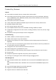
Network Video Recorder User Manual Chapter 1 Introduction 1.1 Front Panel 1.1.1 DS-96000NI-I16(/H) Series Figure 1-1 DS-96000NI-I16(/H) Series Table 1-1 Description No. Name Description 1 Locks or unlocks the panel by the key. Panel lock Returns to the previous menu. Press it twice quickly to switch the main and auxiliary Exit 2 port. In live view mode, press it to enter PTZ control Shortcut buttons interface. Press it to pop up main menu.
Network Video Recorder User Manual 4 Powers on/off device. Solid blue indicates device is powered on. Solid red indicates device is shut down. Power switch Confirms selection in any of the menu modes. Checks the checkbox fields. Switches on/off status. ENTER Plays or pauses the video playing in playback mode. Advances the video by a single frame in single-frame playback mode. Stops/starts auto switch in auto-switch mode.
Network Video Recorder User Manual HDD Solid red: at least one HDD is installed Unlit: no HDD is detected. Blinking red: HDD is reading/writing. Tx/Rx Blinking blue indicates network communication is normal. Ready Solid blue indicates device runs properly. Alarm Solid red indicates alarm occurs. 3 USB interface Universal Serial Bus (USB) ports for additional devices such as USB mouse and USB Hard Disk Drive (HDD). 4 Panel lock Locks or unlocks the panel by the key.
Network Video Recorder User Manual Figure 1-3 Remote Control 1.2.2 Unpairing (Disabling) an IR Remote from a Device To unpair an IR Remote from a device so that the unit cannot control any device functions, proceed as follows: Press the DEV key on the IR Remote. Any existing Device ID# will be erased from the unit’s memory and it will no longer function with the device. (Re)-enabling the IR Remote requires pairing to a device. See “Pairing the IR Remote to a Specific device (optional),” above.
Network Video Recorder User Manual Table 1-3 IR Remote Functions No. Name Function Description •To Turn Power On: -If User Has Not Changed the Default device Device ID# (255): 1.Press Power On/Off button (1). -If User Has Changed the device Device ID#: 1.Press DEV button. 2.Press Number buttons to enter user-defined Device ID#. 3.Press Enter button. 4.Press Power button to start device. •To Turn device Off: -If User Is Logged On: 1.
Network Video Recorder User Manual See “System Configuration” section.
Network Video Recorder User Manual Checks checkbox Play or pause video in Playback mode Advance video a single frame in single-frame Playback mode Stop/start auto switch in auto-switch mode 13 PTZ 14 ESC 15 RESERVED Enter PTZ Control mode Go back to previous screen N/A Reserved Select all items on a list 16 F1 N/A Switch between play and reverse play in Playback mode 17 PTZ Control Adjust PTZ camera iris, focus, and zoom 18 F2 Cycle through tab pages Switch between channels in Synchronous Play
Network Video Recorder User Manual Batteries are fresh and not out of charge. IR receiver is not obstructed. No fluorescent lamp is used nearby If the remote still can’t function properly, please change a remote and try again, or contact the device provider. 1.3 USB Mouse Operation A regular 3-button (Left/Right/Scroll-wheel) USB mouse can also be used with this device. To use a USB mouse: Step 1 Plug USB mouse into one of the USB interfaces on the front panel of the device.
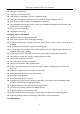
Network Video Recorder User Manual 1.4 Rear Panel Purpose: The interfaces of DS-96000NI-I16 and DS-96000NI-I24 are the same. The interfaces of DS-96000NI-I16/H and DS-96000NI-I24/H are the same. We take the example of DS-96000NI-I16/H series to introduce the rear panel. The difference between DS-96000NI-I16 and DS-96000NI-I16/H is DS-96000NI-I16/H contains the decoding board, that is the module marked as 13 in following figure. Figure 1-4 DS-96000NI-I16/H Series Table 1-5 Panel Description No.
Network Video Recorder User Manual 10 Alarm in Connector for alarm input. Alarm out Connector for alarm output. RS-485 Connector for RS-485 devices. KB Connector for keyboard. 11 GND Ground (needs to be connected when NVR starts up). 12 Power supply Only one power supply module is provided by default. Two modules power supply modules are optional for redundancy. 13 Decoding board Decoding board. Only available for DS-96000NI-I16/H and DS-96000NI-I24/H.
Network Video Recorder User Manual Chapter 2 Getting Started 2.1 Start up the Device Purpose: Proper startup and shutdown procedures are crucial to expanding the life of the device. Before you start: Check that the voltage of the extra power supply is the same with the device’s requirement, and the ground connection is working properly. Step 1 Connect the device power supply interface and electrical socket with delivered power cable.
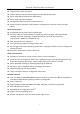
Network Video Recorder User Manual Figure 2-1 Setting Admin Password We highly recommend you create a strong password of your own choosing (Using a minimum of 8 characters, including at least three of the following categories: upper case letters, lower case letters, numbers, and special characters.) in order to increase the security of your product.
Network Video Recorder User Manual Step 1 After the device is activated, you can enter the following interface to configure the device unlock pattern. Step 2 Use the mouse to draw a pattern among the 9 dots on the screen. Release the mouse when the pattern is done. Figure 2-2 Draw the Pattern Connect at least 4 dots to draw the pattern. Each dot can be connected for once only. Step 3 Draw the same pattern again to confirm it. When the two patterns match, the pattern is configured successfully.
Network Video Recorder User Manual 2.4 Login to the Device 2.4.1 Log in via Unlock Pattern Only the admin user has the permission to unlock the device. Please configure the pattern first before unlocking. Please refer to Chapter 2.2 Activate the Device. Step 1 Right click the mouse on the screen and select the menu to enter the interface. Figure 2-3 Draw the Unlock Pattern Step 2 Draw the pre-defined pattern to unlock to enter the menu operation.
Network Video Recorder User Manual Step 1 Select the User Name in the dropdown list. Figure 2-4 Login Interface Step 2 Input password. Step 3 Click OK to log in. When you forget the password of the admin, you can click Forgot Password to reset the password. In the Login dialog box, if you enter the wrong password 7 times, the current user account will be locked for 60 seconds. 2.5 Enter Wizard to Configure Quick Basic Settings By default, the Setup Wizard starts once the device has loaded.
Network Video Recorder User Manual Figure 2-5 Date and Time Settings Step 2 After the time settings, click Next to enter the Network Setup Wizard window, as shown in the following figure. Figure 2-6 Network Settings Step 3 Click Next after you configured the network parameters, which takes you to the HDD Management window.
Network Video Recorder User Manual Figure 2-7 HDD Management Step 4 To initialize the HDD, click the Init button. Initialization removes all the data saved in the HDD. Step 5 Click Next. You enter the Camera Setup interface to add the IP cameras. 1) Click Search to search the online IP Camera. Before adding the camera, make sure the IP camera to be added is in active status. 2) Click the Add to add the camera.
Network Video Recorder User Manual Figure 2-9 Hik-Connect Access Step 7 Click Next to enter the Change Password interface to create the new admin password if required. Figure 2-10 Change Password You can enter click the to show the characters input. 1) Check the checkbox of New Admin Password. 2) Enter the original password in the text field of Admin Password 3) Input the same password in the text field of New Password and Confirm. 4) Check the Unlock Pattern to enable the unlock pattern login.
Network Video Recorder User Manual We highly recommend you create a strong password of your own choosing (Using a minimum of 8 characters, including at least three of the following categories: upper case letters, lower case letters, numbers, and special characters.) in order to increase the security of your product. And we recommend you reset your password regularly, especially in the high security system, resetting the password monthly or weekly can better protect your product.
Network Video Recorder User Manual System Maintenance: 2.7 System Operation 2.7.1 Log out Purpose: After logging out, the monitor turns to the live view mode and if you want to perform any operations, you need to enter user name and password to log in again. Step 1 Click on the menu bar. Step 2 Click Logout. After you have logged out the system, menu operation on the screen is invalid. It is required to input a user name and password to unlock the system. 2.7.
Network Video Recorder User Manual Chapter 3 Camera Management 3.1 Add the IP Cameras 3.1.1 Add the IP Camera Manually Purpose: Before you can get live video or record the video files, you should add the network cameras to the connection list of the device. Before you start: Ensure the network connection is valid and correct, and the IP camera to add has already been activated. Step 1 Click on the main menu bar to enter the Camera Management.
Network Video Recorder User Manual Step 5 Click Add to finish the adding of the IP camera. Step 6 (Optional) Click Continue to Add to continue to add other IP cameras. 3.1.2 Add the Automatically Searched Online IP Cameras Step 1 On the Camera Management interface, click the Online Device panel to expand the Online Device interface. Step 2 Select the automatically searched online devices. Step 3 Click Add.
Network Video Recorder User Manual Step 1 On the camera management interface, select a camera. Step 2 Go to More Settings > Upgrade at the top taskbar. Step 3 Select the firmware upgrade file from the U-flash drive. Step 4 Click Upgrade. Result: The IP camera will reboot automatically after the upgrading completes. 3.4 Configure the Customized Protocols Purpose To connect the network cameras which are not configured with the standard protocols, you can configure the customized protocols for them.
Network Video Recorder User Manual Example: rtsp://192.168.1.55:554/ch1/main/av_stream. The protocol type and the transfer protocols must be supported by the connected IP camera. Step 3 Click OK to save the settings. Result: After adding the customized protocols, you can see the protocol name is listed in the drop-down list.
Network Video Recorder User Manual Chapter 4 Camera Settings 4.1 Configure OSD Settings Purpose: You can configure the OSD (On-screen Display) settings for the camera, including date/time, camera name, etc. Step 1 Go to Camera > Display. Step 2 Select the camera from the drop-down list. Step 3 Edit the name in the Camera Name text field. Step 4 Check the checkbox of the Display Name, Display Date and Display Week if you want to show the information on the image.
Network Video Recorder User Manual 4.2 Configure Privacy Mask Purpose: The privacy mask can be used to protect personal privacy by concealing parts of the image from view or recording with a masked area. Step 1 Go to Camera >Privacy Mask. Step 2 Select the camera to set privacy mask. Step 3 Click the checkbox of Enable to enable this feature. Step 4 Use the mouse to draw a zone on the window. The zones will be marked with different frame colors.
Network Video Recorder User Manual 4.3 Configure the Video Parameters Purpose: You can customize the image parameters including the brightness, contrast, saturation for the live view and recording effect. Step 1 Go to Camera > Display. Step 2 Select the camera from the drop-down list. Step 3 Adjust the slider or click on the up/down arrow to set the value of the brightness, contrast or saturation. Step 4 Click Apply to save the settings. 4.
Network Video Recorder User Manual Exposure: Set the exposure time (1/10000 to 1 sec) of camera. The larger exposure value results in the brighter image. Backlight: Set the wide dynamic range (0 to 100) of the camera. When the surrounding illumination and the object have larger difference in brightness, you should set the WDR value. Image Enhancement: For optimized image contrast enhancement. Step 4 Click the Apply to save the settings.
Network Video Recorder User Manual Chapter 5 Live View Live view shows you the video image getting from each camera in real time. 5.1 Start Live View Click on the main menu bar to enter the live view. You can select a window and double click a camera from the list to play the video from the camera in the selected window.
Network Video Recorder User Manual The fisheye expansion view feature is supported by the DS-7600/7700/8600/9600-I (/P) series device only. The connected camera must support the fisheye view. Step 1 In the live view mode, click the to enter the fisheye expansion mode. Step 2 Select the expansion view mode. 180° Panorama ( ): Switch the live view image to the 180° panorama view. 360° Panorama ( ): Switch the live view image to the 360° panorama view.
Network Video Recorder User Manual 5.1.4 Live View Strategy Step 1 In the live view mode, click mode. to enter the digital zoom operation interface in full screen Step 2 Select the live view strategy to Real-time, Balanced or Fluency. 5.2 Target Detection In live view mode, the target detection function can be used to detect the human motoion/face/vechicle/human body during the last 5 seconds and the following 10 seconds.
Network Video Recorder User Manual 5.3 Configure Live View Settings Live View settings can be customized according to different needs. You can configure the output interface, dwell time for screen to be shown, mute or turning on the audio, the screen number for each channel, etc. Step 1 Go to System > Live View > General. Figure 5-3 Live View-General Step 2 Configure the live view parameters. Video Output Interface: Select the video output to configure.
Network Video Recorder User Manual Figure 5-4 Live View Step 2 Select the video output interface, e.g., HDMI/ VGA or channel-zero. Step 3 Select a window division mode from the toolbar. Step 4 Select a division window, and double-click on the camera from the list to set the camera to the window. You can enter the number in the text field to quickly search the camera from the list. You can also click-and-drag the camera to the desired window on the live view interface to set the camera order.
Network Video Recorder User Manual 5.5 Configure Auto-Switch of Cameras You can set the auto-switch of cameras to play in different display modes. Step 1 Go to System > Live View > General. Step 2 Set the video output interface, live view mode and dwell time. Video Output Interface: Select the video output interface. Live View Mode: Select the display mode for live view, e.g., 2*2, 1*5, etc. Dwell Time: The time in seconds to dwell between switching of cameras when enabling auto-switch.
Network Video Recorder User Manual Result: You can view all of the channels in one screen using the CMS or web browser. 5.7 Using an Auxiliary Monitor Certain features of the Live View are also available while in an Aux monitor. These features include: Single Screen: Switch to a full screen display of the selected camera. Camera can be selected from a dropdown list. Multi-screen: Switch between different display layout options. Layout options can be selected from a dropdown list.
Network Video Recorder User Manual Chapter 6 PTZ Control 6.1 PTZ Control Wizard Before you start Please make sure the connected IP camera supports the PTZ function and is properly connected. Purpose Follow the PTZ control wizard to guide you through the basic PTZ operation. Step 1 Click on the quick settings toolbar of the PTZ camera live view. The PTZ control wizard pops up as below. Figure 6-1 PTZ Control Wizard Step 2 Follow the wizard to adjust the PTZ view, focus, and zoom in/out the camera.
Network Video Recorder User Manual Step 1 Click on the quick settings toolbar of the PTZ camera live view. The PTZ control panel displays on the right of the interface. Step 2 Click PTZ Parameters Settings to set the PTZ parameters. Figure 6-2 PTZ Parameters Settings Step 3 Edit the parameters of the PTZ camera. All the parameters should be exactly the same as the PTZ camera parameters. Step 4 Click OK to save the settings. 6.
Network Video Recorder User Manual The PTZ control panel displays on the right of the interface. Step 2 Use the directional buttons on the PTZ control panel to wheel the camera to the location where you want to set preset, and the zoom and focus operations can be recorded in the preset as well. Step 3 Click in the lower right corner of live view to set the preset. Figure 6-3 Set Preset Step 4 Select the preset No. (1~255) from the drop-down list. Step 5 Enter the preset name in the text field.
Network Video Recorder User Manual Figure 6-6 Call Preset (2) 6.3.3 Set a Patrol Purpose: Patrols can be set to move the PTZ to different key points and have it stay there for a set duration before moving on to the next key point. The key points are corresponding to the presets. Step 1 Click on the quick settings toolbar of the PTZ camera live view. The PTZ control panel displays on the right of the interface. Step 2 Click Patrol to configure patrol.
Network Video Recorder User Manual Figure 6-9 Key Point Configuration 1) Configure key point parameters. Preset: It determines the order at which the PTZ will follow while cycling through the patrol. Speed: It defines the speed at which the PTZ will move from one key point to the next. Duration: It refers to the time span to stay at the corresponding key point. 2) Click Apply to save the key points to the patrol. Step 6 (Optional) Click to edit the added key point.
Network Video Recorder User Manual The PTZ control panel displays on the right of the interface. Step 2 Click Patrol on the PTZ control panel. Figure 6-11 Patrol Configuration Step 3 Select a patrol in the text field. Step 4 Click Call to call it. Step 5 (Optional) Click Stop to stop calling it. 6.3.5 Set a Pattern Purpose: Patterns can be set by recording the movement of the PTZ. You can call the pattern to make the PTZ movement according to the predefined path.
Network Video Recorder User Manual 6.3.6 Call a Pattern Purpose: Follow the procedure to move the PTZ camera according to the predefined patterns. Step 1 Click on the quick settings toolbar of the PTZ camera live view. The PTZ control panel displays on the right of the interface. Step 2 Click Pattern to configure pattern. Figure 6-13 Pattern Configuration Step 3 Select a pattern in the text field. Step 4 Click Call to call it. Step 5 (Optional) Click Stop to stop calling it. 6.3.
Network Video Recorder User Manual The speed dome starts linear scan from the left limit to the right limit, and you must set the left limit on the left side of the right limit, as well the angle from the left limit to the right limit should be no more than 180º. 6.3.8 Call Linear Scan Before operating this function, make sure the connected camera supports the linear scan and is in HIKVISION protocol. Purpose: Follow the procedure to call the linear scan in the predefined scan range.
Network Video Recorder User Manual Park (Patrol 1): The dome starts moving according to the predefined patrol 1 path after the park time. Park (Preset 1): The dome moves to the predefined preset 1 location after the park time. The park time can only be set via the speed dome configuration interface. The value is 5s by default. Step 3 Click Stop Park (Quick Patrol), Stop Park (Patrol 1) or Stop Park (Preset 1) to inactivate it. 6.
Network Video Recorder User Manual Table 6-1 Description of Aux Functions Icons Icon Description Light on/off Wiper on/off 3D positioning Center 60
Network Video Recorder User Manual Chapter 7 Storage 7.1 Storage Device Management 7.1.1 Install the HDD Before startup of the device, install and connect the HDD to the device. Refer to the Quick Start Guide for the installation instructions. 7.1.2 Add the Network Disk You can add the allocated NAS or disk of IP SAN to device, and use it as network HDD. Up to 8 network disks can be added. Adding NAS Step 1 Go to Storage > Storage Device. Step 2 Click Add to enter the Custom Add interface.
Network Video Recorder User Manual Figure 7-1 Add NAS Disk Step 7 Select the NAS disk from the list shown below, or you can manually enter the directory in the text field of NetHDD Directory. Step 8 Click the OK to complete the adding of the NAS disk. Result: After having successfully added the NAS disk, return to the HDD Information menu. The added NetHDD will be displayed in the list. Adding IP SAN Step 1 Go to Storage > Storage Device. Step 2 Click Add to enter the Custom Add interface.
Network Video Recorder User Manual Up to 1 IP SAN disk can be added. Figure 7-2 Add IP SAN Disk Result: After having successfully added the IP SAN disk, return to the HDD Information menu. The added NetHDD will be displayed in the list. If the installed HDD or NetHDD is uninitialized, please select it and click the Init button for initialization. 7.1.
Network Video Recorder User Manual Figure 7-3 Set eSATA Mode Step 3 When the eSATA type is selected to Record/Capture, enter the storage device interface. Step 4 Edit the property of the selected eSATA, or initialize it is required. 7.2 Storage Mode 7.2.1 Configure HDD Group Purpose: Multiple HDDs can be managed in groups. Video from specified channels can be recorded onto a particular HDD group through HDD settings. Step 1 Go to Storage> Storage Device.
Network Video Recorder User Manual Figure 7-5 Local HDD Settings Step 4 Select the Group number for the current HDD. Step 5 Click OK. Regroup the cameras for HDD if the HDD group number is changed. Step 6 Go to Storage> Storage Mode. Step 7 Check the checkbox of Group tab. Step 8 Select the group No. from the list. Step 9 Check the checkbox to select the IP camera (s) to record/capture on the HDD group.
Network Video Recorder User Manual Figure 7-6 Storage Mode-HDD Group Step 10 Click Apply. Reboot the device to activate the new storage mode settings. 7.2.2 Configure HDD Quota Purpose: Each camera can be configured with allocated quota for the storage of recorded files or captured pictures. Step 1 Go to Storage> Storage Mode. Step 2 Check the checkbox of Quota tab. Step 3 Select a camera to set quota. Step 4 Enter the storage capacity in the text fields of Max. Record Capacity (GB) and Max.
Network Video Recorder User Manual Figure 7-7 Storage Mode-HDD Quota Step 5 (Optional) You can click Copy to if you want to copy the quota settings of the current camera to other cameras. Step 6 Click the Apply button to apply the settings. Reboot the device to activate the new storage mode settings. When the quota capacity is set to 0, all cameras will use the total capacity of HDD for record and picture capture. 7.2.
Network Video Recorder User Manual Figure 7-8 Storage Mode Step 2 Select Mode as Smart Release. Step 3 Adjust the Quota Radio between the normal video and important video. You can view the Estimated Saving Time for the continuous video and import video. Estimated Saving Time: Calculated based on the quota radio, storage capacity, and video size of last week. Expired continuous videos will be deleted. The time updates every minute. Step 4 Click Apply.
Network Video Recorder User Manual Bitrate: The bit rate (in kbit/s or Mbit/s) is often referred to as speed, but actually defines the number of bits/time unit and not distance/time unit. Enable H.264+ Mode: The H.264+ mode helps to ensure the high video quality with a lowered bitrate. It can effectively reduces the need of bandwith and HDD storage space.
Network Video Recorder User Manual Figure 7-9 Advanced Record Settings Record Audio: Check the checkbox to enable or disable audio recording. Pre-record: The time you set to record before the scheduled time or event. For example, when an alarm triggers the recording at 10:00, and if you set the pre-record time as 5 seconds, the camera records at 9:59:55. Post-record: The time you set to record after the event or the scheduled time.
Network Video Recorder User Manual Refer to Chapter 7.1.2 Add the Network Disk for network HDD connections. Step 1 Go to Storage > Recording Schedule. Figure 7-10 Recording Schedule Step 2 Select a camera. Step 3 Check Enable Schedule. Step 4 Select a record type. The record type can be Continuous, Motion Detection, Alarm, Motion | Alarm, Motion & Alarm, and Event. Different recording types are configurable. Continuous: scheduled recording. Event: recording triggered by all event triggered alarm.
Network Video Recorder User Manual The all-day continuous recording is configured for the device by factory default. Step 7 Click Apply to save the settings. To enable Motion, Alarm, M | A (motion or alarm), M & A (motion and alarm) and Event triggered recording and capture, you must configure the motion detection settings, alarm input settings and other events as well. Please refer to Chapter 10 and Chapter 12 for details. 7.
Network Video Recorder User Manual Step 1 Go to System > Event. Step 2 Configure the event detection and select the channel (s) to trigger the recording when event occurs. Refer to Chapter 10 and Chapter 12 VCA Event Alarm for details. Step 3 Go to Camera > Encoding Parameters > Recording Parameters. Step 4 Set the event main stream/sub-stream recording parameters for the camera. Step 5 Go to Storage > Recording Schedule. Step 6 Select the recording type to Event.
Network Video Recorder User Manual Step 4 Select the camera to configure the picture capture. Figure 7-11 Set Picture Capture Schedule Step 5 Set the picture capture schedule. Refer to Chapter 7.4 Configure Recording Schedule for details. 7.10 Configure Holiday Recording and Capture Purpose: Follow the steps to configure the record or capture schedule on holiday for that year. You may want to have different plan for recording and capture on holiday. Step 1 Go to System > Holiday Settings.
Network Video Recorder User Manual Figure 7-12 Edit Holiday Settings 1) 2) 3) 4) Edit the holiday name. Select the mode to by date, by week or by month. Set the start and end date of the holiday. Click OK. Step 4 Set the schedule for the holiday recording. Refer to Chapter 7.4 Configure Recording Schedule for details.
Network Video Recorder User Manual 7.11 Configure Redundant Recording and Capture Purpose: Enabling redundant recording and capture, which means saving the record files and captured pictures not only in the R/W HDD but also in the redundant HDD, will effectively enhance the data safety and reliability. . You must set the storage mode to Group before you set the HDD property to Redundancy. For detailed information, please refer to Chapter 7.2.1 Configure HDD Group.
Network Video Recorder User Manual Figure 7-14 Record Parameters Step 6 Check the checkbox of Redundant Record/Capture. Step 7 Click OK to save settings.
Network Video Recorder User Manual Chapter 8 Disk Array Purpose: Disk array is a data storage virtualization technology that combines multiple physical disk drive components into a single logical unit. An array stores data over multiple HDDs to provide enough redundancy so that data can be recovered if one disk fails. Data is distributed across the drives in one of several ways called "RAID levels", depending on what level of redundancy and performance is required. 8.
Network Video Recorder User Manual 8.1.2 One-Touch Creation Purpose: One-touch configuration helps you to quickly create the disk array. By default, the array type created by one-touch configuration is RAID 5. Before you start: Enable RAID function. For details, refer to Chapter 8.1.1 Enable RAID. Install at least 3 HDDs. If more than 10 HDDs are installed, 2 arrays will be created.
Network Video Recorder User Manual Table 8-1 Create Array Step 3 Enter the array name. Step 4 Select RAID Level as RAID 0, RAID 1, RAID 5, RAID 6, or RAID 10 as required. Step 5 Select the physical disks to constitute array. Table 8-2 Required Number of HDD RAID Level Required Number of HDD RAID 0 At least 2 HDDs. RAID 1 At least 2 HDDs. RAID 5 At least 3 HDDs. RAID 6 At least 4 HDDs. RAID 10 The number of HDD must be an even ranges from 4 to 16. Step 6 Click OK.
Network Video Recorder User Manual 8.2 Rebuild Array Purpose: The status of array includes Functional, Degraded and Offline. To ensure the high security and reliability of the data stored in array, you should take immediate and proper maintenance at arrays according their status. Functional: No disk loss in the array. Offline: The number of lost disks has exceeded the limit. Degraded: If amount of HDD fail in array, array degrades. You should recover it to Functional by array rebuilding. 8.2.
Network Video Recorder User Manual 8.2.3 Manually Rebuild Array Purpose: If no hot spare disks are configured, rebuild the degraded array manually. Before you start: At least one available physical disk should exist for rebuilding the array. Step 1 Go to Storage > RAID Setup > Array. Figure 8-6 Array List Step 2 Click of degraded array. Figure 8-7 Rebuild Array Step 3 Select the available physical disk. Step 4 Click OK.
Network Video Recorder User Manual 8.3 Delete Array Deleting array will delete all the data saved in it. Step 1 Go to Storage > RAID Setup > Array. Figure 8-8 Array List Step 2 Click of array to delete. Figure 8-9 Attention Step 3 Click Yes on the popup message box.
Network Video Recorder User Manual 8.4 Check and Edit Firmware Purpose: You can view the information of the firmware and set the background task speed on the Firmware interface. Step 1 Go to Storage > RAID Setup > Firmware. Figure 8-10 Firmware Step 2 Optionally, set the Background Task Speed. Step 3 Click Apply.
Network Video Recorder User Manual Chapter 9 File Management 9.1 Search and Export All Files 9.1.1 Search Files Purpose Specify detailed conditions to search videos and pictures. Step 1 Go to File Management > All Files. Step 2 Specify detailed conditions, including time, camera, event type, etc. Figure 9-1 Search All Files Step 3 Click Search to display results. The matched files will be displayed. 9.1.
Network Video Recorder User Manual 9.2 Search and Export Human Files 9.2.1 Search Human Files Purpose Specify detailed conditions to search human pictures and videos. Before you start Configure human body detection function for the cameras you want to search and export human pictures and videos. Step 1 Go to File Management > Human Files. Step 2 Select Time and Camera to search. Figure 9-2 Search Human Files Step 3 Click Search to display results. The matched files are displayed in thumbnail or list.
Network Video Recorder User Manual 9.3 Search and Export Vehicle Files 9.3.1 Search Vehicle Files Purpose Specify detailed conditions to search vehicle pictures and videos. Before you start Configure vehicle detection function for the cameras you want to search and export vehicle pictures and videos. Step 1 Go to File Management > Vehicle Files. Step 2 Specify detailed conditions, including Time, Camera, Plate No., and Area/Country. Figure 9-3 Search Vehicle Files Step 3 Click Search to display results.
Network Video Recorder User Manual 9.4 Search History Operation 9.4.1 Save Search Condition Purpose You can save the search conditions for future reference and quick search. Step 1 Go to File Management > All Files/People Appearance File/Vehicle File. Step 2 Set the search conditions. Step 3 Click Save. Step 4 Enter a name in text field and click Finished. The saved search conditions will be displayed in search history list. 9.4.
Network Video Recorder User Manual Chapter 10 Playback 10.1 Play Video Files 10.1.1 Instant Playback Instant Playback enables the device to play the recorded video files in last five minutes. If no video is found, it means there is no recording during the last five minutes. Step 1 On the live view window of the selected camera, move the cursor to the window bottom to access the toolbar. Step 2 Click to start instant playback. Figure 10-1 Playback Interface 10.1.2 Play Normal Video Step 1 Go to Playback.
Network Video Recorder User Manual Figure 10-2 Playback Interface Figure 10-3 Toolbar of Playback Click the channel(s) to execute simultaneous playback of multiple channels. The playing speed of 256X is supported. 10.1.3 Play Smart Searched Video In the smart playback mode, the device can analyze the video containing the motion, line or intrusion detection information, mark it in red color and play the smart searched video. The smart playback must be in the single-channel playing mode.
Network Video Recorder User Manual Figure 10-4 Playback by Smart Search Step 5 Set the rules and areas for smart search of line crossing detection, intrusion detection or motion detection event triggered recording. Line Crossing Detection 5) Click the icon. 6) Click on the image to specify the start point and end point of the line. Intrusion Detection 7) Click the icon. 8) Specify 4 points to set a quadrilateral region for intrusion detection. Only one region can be set.
Network Video Recorder User Manual Figure 10-5 Custom Search Step 5 Click Search. Figure 10-6 Custom Searched Video Files Step 6 On the search results interface, select a file and click to start playing the video. 10.1.5 Video Synopsis Purpose: Video synopsis is an approach to create a short video summary of a long video. It tracks and analyzes moving objects (also called events), and converts video streams into a database of objects and activities.
Network Video Recorder User Manual Step 2 Click in toolbar. Figure 10-7 Synopsis Playback Step 3 Select a camera in channel list. Step 4 Specify Start Time and End Time. The duration must be within 24 hours. Step 5 Click Search to start play. Step 6 Optionally, double click a target on the playback window. A 60-second video of 30 seconds before and after the time will be played. 10.1.
Network Video Recorder User Manual Max. 64 tags can be added to a single video file. Edit Tag Files Step 1 Go to Playback. Step 2 Click Tag. The available tags are white marked and displayed in the time bar. Step 3 Point the white marked tag in the time bar to access the tag information. Figure 10-8 Edit Tag Files Step 4 Click to edit the tag name. Step 5 Click OK. Play Tag Files Step 1 Go to Playback. Step 2 Click Custom Search on the left bottom to enter the Search Condition interface.
Network Video Recorder User Manual Figure 10-9 Tag Search Step 4 Click Search. Figure 10-10 Searched Tag Files Step 5 On the search results interface, select a tag file and click to start playing the video. 10.1.7 Play Event Files Purpose Play back video files on one or several channels searched by event type (e.g., alarm input, motion detection, line crossing detection, face detection, vehicle detection, etc.). Step 1 Go to Playback.
Network Video Recorder User Manual Step 5 On the search results interface, select an event video file/picture file and double click to start playing the video. Figure 10-11 Event Files Step 6 You can click or button to play 30s backward or forward. Refer to Chapter 10 and Chapter 12 VCA Event Alarm for details for event and alarm settings. Refer to Chapter 7.7 Configure Event Triggered Recording for the event triggered recording/capture settings. 10.1.
Network Video Recorder User Manual According to the defined number of split-screens, the video files on the selected date can be divided into average segments for playback. E.g., if there are video files existing between 16:00 and 22:00, and the 6-screen display mode is selected, then it can play the video files for 1 hour on each screen simultaneously. 10.1.9 Play Log Files Purpose: Play back record file(s) associated with channels after searching system logs. Step 1 Go to Maintenance>Log Information.
Network Video Recorder User Manual Step 1 Go to Playback. Step 2 Click the icon at the left bottom corner. Step 3 Select and click the button or double click to play the file. 10.2 Playback Operations 10.2.1 Set Play Strategy in Smart/Custom Mode Purpose: When you are in the smart or custom video playback mode, you can set the playing speed separately for the normal video and the smart/custom video, or you can select to skip the normal video.
Network Video Recorder User Manual : Set the start time and end time of the video clipping. : Export the video clips to the local storage device. 10.2.3 Switch between Main Stream and Sub-Stream You can switch between the main stream and the sub-stream during the playback. : Play the video in main stream. : Play the video in sub-stream. The encoding parameters for the main stream and sub-stream can be configured in Storage > Encoding Parameters. 10.2.
Network Video Recorder User Manual 360° Panorama ( PTZ Expansion ( ): The PTZ Expansion is the close-up view of some defined area in the fisheye view or panorama expansion, and it supports the electronic PTZ function, which is also called e-PTZ. Radial Expansion ( ): In the radial expansion mode, the whole wide-angle view of the fisheye camera is displayed. This view mode is called Fisheye View because it approximates the vision of a fish’s convex eye.
Network Video Recorder User Manual Chapter 11 Event and Alarm Settings 11.1 Configure Arming Schedule Step 1 Select the Arming Schedule tab. Step 2 Choose one day of a week and set the time segment. Up to eight time periods can be set within each day. Time periods shall not be repeated or overlapped. Figure 11-1 Set Arming Schedule Step 3 Click Apply to save the settings. 11.2 Configure Alarm Linkage Actions Step 1 Click Linkage Action to set the alarm linkage actions.
Network Video Recorder User Manual Figure 11-2 Set Linkage Actions Step 2 Select the normal linkage actions, trigger alarm output or trigger recording channel. Full Screen Monitoring When an alarm is triggered, the local monitor displays in full screen the video image from the alarming channel configured for full screen monitoring. If alarms are triggered simultaneously in several channels, their full-screen images will be switched at an interval of 10 seconds (default dwell time).
Network Video Recorder User Manual It will send an exception or alarm signal to the remote alarm host when an event occurs. The alarm host refers to the PC installed with Remote Client. The alarm signal will be transmitted automatically at detection mode when remote alarm host is configured. Please refer to Chapter 14.8 Configure Ports for alarm host configuration. Send Email It will send an email with alarm information to the user when an alarm is detected. Please refer to 14.
Network Video Recorder User Manual Figure 11-3 Set Motion Detection Step 2 Select the camera to configure the motion detection. Step 3 Check Enable. Step 4 Set the motion detection area. Full screen: click to set the full-screen motion detection for the image. Customized area: use the mouse to click and drag on the preview screen to draw the customized motion detection area (s). You can click Clear to clear the current motion detection area settings and draw again. Step 5 Set sensitivity (0-100).
Network Video Recorder User Manual 11.4 Configure Video Loss Alarm Purpose: The video loss detection enables to detect video loss of a channel and take alarm response action(s). Step 1 Go to System> Event>Normal Event>Video Loss Figure 11-4 Set Video Loss Detection Step 2 Select the camera to configure the video loss detection. Step 3 Check Enable. Step 4 Set the arming schedule. Refer to Chapter 11.1 Configure Arming Schedule. Step 5 Set the linkage actions. Refer to Chapter 11.
Network Video Recorder User Manual 11.5 Configure Video Tampering Alarm Purpose: The video tampering detection enables to trigger alarm when the camera lens is covered and take alarm response action(s). Step 1 Go to System> Event>Normal Event>Video Tampering. Step 2 Select the camera to configure the video tampering detection. Figure 11-5 Set Video Tampering Setting Step 3 Check Enable. Step 4 Set the video tampering area.
Network Video Recorder User Manual 11.6 Configure Sensor Alarms Purpose: Set the handling action of an external sensor alarm. 11.6.1 Configure Alarm Input Step 1 Go to System> Event>Normal Event>Alarm Input Step 2 Select an alarm input item from the list and click . Figure 11-6 Alarm Input Step 1 Select the alarm input type to N.C or N.O. Step 2 Edit the alarm name. Step 3 Check the radio button of Input. Step 4 Set the arming schedule. Refer to Chapter 11.1 Configure Arming Schedule.
Network Video Recorder User Manual 11.6.2 Configure One-Key Disarming The one-key disarming enables the device to disarm the alarm input 1 by one-key operation. Step 1 Go to System> Event>Normal Event>Alarm Input Step 2 Select the alarm input1 item from the list and click . Step 3 Select the alarm input type to N.C or N.O. Step 4 Edit the alarm name. Step 5 Check the radio button of Enable One-Key Disarming.
Network Video Recorder User Manual Step 1 Go to System> Event>Normal Event>Alarm Output. Step 2 Select an alarm output item from the list and click . Step 3 Edit the alarm name. Step 4 Select the dwell time (the alarm duration) from 5s to 600s, or Manually Clear. Manually Clear: you should manually clear the alarm when the alarm occurs. Refer to Chapter 11.9 Trigger or Clear Alarm Output Manually for detailed instructions. Step 5 Set the arming schedule. Refer to Chapter 11.1 Configure Arming Schedule.
Network Video Recorder User Manual 11.7 Configure Exceptions Alarm The exception events can be configured to take the event hint in the live view window, trigger alarm output and linkage actions. Step 1 Go to System> Event>Normal Event>Exception. Step 2 (Optional) Enable the event hint if you want to display the event hint in the live view window. 1) Check the checkbox of Enable Event Hint. 2) Click to select the exception type (s) to take the event hint.
Network Video Recorder User Manual Figure 11-10 Exceptions Handling Step 4 Set the normal linkage and alarm output triggering. Refer to Chapter 11.2 Configure Alarm Linkage Actions.
Network Video Recorder User Manual 11.8 Alarm Linkage Actions Purpose: Alarm linkage actions will be activated when an alarm or exception occurs, including Event Hint Display, Full Screen Monitoring, Audible Warning (buzzer), Notify Surveillance Center, Trigger Alarm Output and Send Email. 11.8.1 Configure Auto-switch Full Screen Monitoring When an alarm is triggered, the local monitor displays in full screen the video image from the alarming channel configured for full screen monitoring.
Network Video Recorder User Manual Step 1 Go to System > Network > Advanced > More Settings. Step 2 Set the alarm host IP and alarm host port. Step 3 Go to the Linkage Action interface of the alarm detection (e.g., motion detection, video tampering, face detection, etc.). Step 4 Select the Notify Surveillance Center. 11.8.4 Configure Email Linkage The system can send an email with alarm information to a user or users when an alarm is detected. Please refer to Chapter 14.
Network Video Recorder User Manual Step 1 Go to the Linkage Action interface of the alarm input or VCA detection (e.g., face detection, line crossing detection, intrusion detection, etc.). Step 2 Select the PTZ Linkage. Step 3 Select the camera to perform the PTZ actions. Step 4 Select the preset/patrol/pattern No. to call when the alarm events occur. Figure 11-11 PTZ Linkage You can set one PTZ type only for the linkage action each time. 11.
Network Video Recorder User Manual Figure 11-12 Alarm Output 115
Network Video Recorder User Manual Chapter 12 VCA Event Alarm The device supports receiving the VCA detections sent by connected IP cameras. Enable and configure the VCA detection on the IP camera settings interface first. VCA detections must be supported by the connected IP camera. Refer to the User Manual of Network Camera for the detailed instructions for the VCA detection. 12.1 Face Detection Purpose: Face detection function detects the face appears in the surveillance scene.
Network Video Recorder User Manual Step 4 Check Enable Face Detection. Step 5 Optionally, check Save VCA Picture to save the captured pictures of face detection. Step 6 Drag the Sensitivity slider to set the detection sensitivity. Sensitivity range: [1-5]. The higher the value is, the more easily the face can be detected. Step 7 Set the arming schedule. Refer to Chapter 11.1 Configure Arming Schedule. Step 8 Set the linkage actions. Refer to Chapter 11.2 Configure Alarm Linkage Actions. Step 9 Click Apply.
Network Video Recorder User Manual Step 5 Optionally, check Save VCA Picture to save the captured pictures of vehicle detection. Step 6 Set the arming schedule. Refer to Chapter 11.1 Configure Arming Schedule. Step 7 Set the linkage actions. Refer to Chapter 11.2 Configure Alarm Linkage Actions. Step 8 Configure rules, including Area Settings, Picture, Overlay Content, and Blacklist and Whitelist. Area Settings: Up to 4 lanes are selectable. Step 9 Click Save.
Network Video Recorder User Manual Step 4 Check Enable Line Crossing Detection checkbox. Step 5 Optionally, check Save VCA Picture to save the captured pictures of line crossing detection. Step 6 Follow the steps to set the line crossing detection rules and detection areas. 3) Select an Arming Region to configure. Up to 4 arming regions are selectable. 4) Select the Direction as A<->B, A->B, or A<-B. A<->B: Only the arrow on the B side shows.
Network Video Recorder User Manual Figure 12-4 Set Arming Schedule Step 11 Click Apply to save the settings. Step 12 Configure Alarm Linkage Actions. Step 13 Click Apply. 12.4 Intrusion Detection Purpose: Intrusion detection function detects people, vehicle or other objects which enter and loiter in a pre-defined virtual region, and some certain actions can be taken when the alarm is triggered. Step 1 Go to System > Event > Smart Event. Step 2 Click Intrusion.
Network Video Recorder User Manual Figure 12-5 Intrusion Detection Step 3 Select a Camera to configure. Step 4 Check Enable Intrusion Detection. Step 5 Optionally, check Save VCA Picture to save the captured pictures of intrusion detection. Step 6 Follow the steps to set the detection rules and detection areas. 1) Select a Virtual Panel to configure. Up to 4 virtual panels are selectable. 2) Drag the sliders to set Time Threshold, Sensitivity, and Percentage.
Network Video Recorder User Manual Step 8 Set the linkage actions. Refer to Chapter 11.2 Configure Alarm Linkage Actions. Step 9 Click Apply. 12.5 Region Entrance Detection Purpose: Region entrance detection function detects objects that enter a pre-defined virtual region from the outside place. Step 1 Go to System Management > Event Settings > Smart Event. Step 2 Click the Region Entrance Detection item. Figure 12-6 Region Entrance Detection Step 3 Select a Camera to configure.
Network Video Recorder User Manual 9) Click Draw Region and draw a quadrilateral in the preview window by specifying four vertexes of the detection region. Step 7 Configure Arming Schedule and Linkage Action. Step 8 Click Apply. 12.6 Region Exiting Detection Purpose: Region exiting detection function detects objects that exit from a pre-defined virtual region. Step 1 Go to System > Event > Smart Event. Step 2 Click Region Exiting. Figure 12-7 Region Exiting Detection Step 3 Select a Camera to configure.
Network Video Recorder User Manual 12) Click Draw Region and draw a quadrilateral in the preview window by specifying four vertexes of the detection region. Step 7 Set the arming schedule. Refer to Chapter 11.1 Configure Arming Schedule. Step 8 Set the linkage actions. Refer to Chapter 11.2 Configure Alarm Linkage Actions. Step 9 Click Apply. 12.
Network Video Recorder User Manual 13) Select an Arming Region to configure. Up to 4 regions are selectable. 14) Drag the sliders to set Time Threshold and Sensitivity. Time Threshold: The time of the objects left over in the region. If the value is 10, alarm is triggered after the object is left and stayed in the region for 10s. Its range is [5s-20s]. Sensitivity: Similarity degree of the background image. The higher the value is, the more easily the detection alarm can be triggered.
Network Video Recorder User Manual Step 3 Select a Camera to configure. Step 4 Check Enable Object Removable Detection. Step 5 Optionally, check Save VCA Picture to save the captured pictures of object removable detection. Step 6 Follow the steps to set the detection rules and detection areas. 16) Select an Arming Region to configure. Up to 4 regions are selectable. 17) Drag the sliders to set Time Threshold and Sensitivity. Time Threshold: The time of the objects removed from the region.
Network Video Recorder User Manual Step 3 Select a Camera to configure. Step 4 Optionally, check Save VCA Picture to save the captured pictures of audio exception detection. Step 5 Follow the steps to set the detection rules. 4) Select the Exception Detection tab. 5) Check the checkboxes of Audio Loss Exception, Sudden Increase of Sound Intensity Detection, or Sudden Decrease of Sound Intensity Detection. Audio Loss Exception: Detects the sound steep rise in the surveillance scene.
Network Video Recorder User Manual Figure 12-11 Sudden Scene Change Step 3 Select a Camera to configure. Step 4 Check Enable Sudden Scene Change Detection. Step 5 Optionally, check Save VCA Picture to save the captured pictures of sudden scene change detection. Step 6 Drag the Sensitivity slider to set the detection sensitivity. Sensitivity range: [1-100]. The higher the value is, the more easily the change of scene can trigger the alarm. Step 7 Set the arming schedule. Refer to Chapter 11.
Network Video Recorder User Manual Figure 12-12 Defocus Detection Step 3 Select a Camera to configure. Step 4 Check Enable Defocus Detection. Step 5 Optionally, check Save VCA Picture to save the captured pictures of defocus detection. Step 6 Drag the Sensitivity slider to set the detection sensitivity. Sensitivity range: [1-100]. The higher the value is, the more easily the defocus image can be detected. Step 7 Set the arming schedule. Refer to Chapter 11.1 Configure Arming Schedule.
Network Video Recorder User Manual Figure 12-13 FIR Alarm Step 3 Select a Camera to configure. Step 4 Check PIR Alarm. Step 5 Optionally, check Save VCA Picture to save the captured pictures of PIR alarm. Step 6 Set the arming schedule. Refer to Chapter 11.1 Configure Arming Schedule. Step 7 Set the linkage actions. Refer to Chapter 11.2 Configure Alarm Linkage Actions. Step 8 .Click Apply.
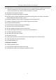
Network Video Recorder User Manual Chapter 13 Smart Analysis With the configured VCA detection, the device supports the smart analysis for people counting and heat map. 13.1 People Counting Purpose: The Counting is used to calculate the number of people entered or left a certain configured area and form in daily/weekly/monthly/annual reports for analysis. Step 1 Go to Smart Analysis > Counting. Step 2 Select the camera.
Network Video Recorder User Manual Step 3 Select the report type as Daily Report, Weekly Report, Monthly Report, or Annual Report. Step 4 Set the Data to analyze. Figure 13-2 Heat Map Interface Step 5 Click Counting. Then the results displayed in graphics marked in different colors will show. As shown in the figure above, red color block (255, 0, 0) indicates the most welcome area, and blue color block (0, 0, 255) indicates the less-popular area.
Network Video Recorder User Manual Chapter 14 Network Settings 14.1 Configure TCP/IP Settings Purpose TCP/IP settings must be properly configured before you can operate the device over network. Step 1 Go to System > Network > TCP/IP. Figure 14-1 TCP/IP Settings Step 2 Select Net-Fault Tolerance or Multi-Address Mode under Working Mode. Net-Fault Tolerance: The two NIC cards use the same IP address, and you can select the main NIC to LAN1 or LAN2.
Network Video Recorder User Manual Check Enable DHCP to obtain IP settings automatically if a DHCP server is available in the network. Valid range of MTU value is 500 to 9676. Step 4 Click Apply. 14.2 Configure Guarding Vision Purpose Guarding Vision enables the mobile phone application and the service platform page (dev.guardingvision.com) to access and manage your connected NVR, providing a convenient remote access to the surveillance system.
Network Video Recorder User Manual For more detailed instructions of Guarding Vision, please refer to the help on dev.guardingvision.com. 14.3 Configure DDNS Purpose You can set Dynamic DNS service for network access. Different DDNS modes are available: DynDNS, PeanutHull, and NO-IP. Before You Start You must register DynDNS, PeanutHull and NO-IP services with your ISP before configuring DDNS settings. Step 1 Go to System > Network > TCP/IP > DDNS. Step 2 Check Enable.
Network Video Recorder User Manual 14.4 Configure PPPoE If the device is connected to Internet through PPPoE, you need to configure user name and password accordingly under System > Network > TCP/IP > PPPoE. Contact your Internet service provider for details about PPPoE service. 14.5 Configure NTP Purpose Connection to a network time protocol (NTP) server can be configured on your device to ensure the accuracy of system date and time. Step 1 Go to System > Network > TCP/IP > NTP.
Network Video Recorder User Manual 14.6 Configure SNMP Purpose You can configure SNMP settings to get device status and parameter information. Before You Start Download the SNMP software to receive device information via SNMP port. By setting the trap address and port, the device is allowed to send alarm event and exception message to the surveillance center. Step 1 Go to System > Network > Advanced > SNMP. Figure 14-5 SNMP Settings Step 2 Check Enable.
Network Video Recorder User Manual 14.7 Configure Email Purpose The system can be configured to send an Email notification to all designated users when a specified event occur, such as an alarm or motion event is detected, or the administrator password is changed, etc. Before You Start The device must be connected to a local area network (LAN) that contains an SMTP mail server.
Network Video Recorder User Manual Select Receivers: Select the receiver. Up to 3 receivers can be configured. Receiver: The name of the receiver. Receiver's Address: The Email address of user to be notified. Enable Attached Picture: Check to enable the function if you want to send email with attached alarm images. The interval is the time between two adjacent alarm images. Step 3 Click Apply. Step 4 (Optional) Click Test to send a test email. 14.
Network Video Recorder User Manual Figure 14-7 Port Settings 140
Network Video Recorder User Manual Chapter 15 Hot Spare Device Backup Purpose: The device can form an N+1 hot spare system. The system consists of several working devices and a hot spare device; when the working device fails, the hot spare device switches into operation, thus increasing the reliability of the system. Please contact dealer for details of models which support the hot spare function.
Network Video Recorder User Manual The camera connection will be disabled when the device works in the hot spare mode. It is highly recommended to restore the defaults of the device after switching the working mode of the hot spare device to normal mode to ensure the normal operation afterwards. 15.2 Set Working Device Step 1 Go to System > Hot Spare. Step 2 Set the Work Mode as Normal Mode. Step 3 Check Enable. Step 4 Enter the IP address, user name, and password of hot spare device.
Network Video Recorder User Manual Table 15-1 Working Status Descrption Working Status Description No record The working device works properly. Backing up The working device gets offline, the hot spare device will record the video of the IP camera connected to the working device for backup The record backing up can be functioned for 1 working device at a time. Synchronizing The working device comes online, the lost video files will be restored by the record synchronization function.
Network Video Recorder User Manual Chapter 16 System Maintenance 16.1 Storage Device Maintenance 16.1.1 Configure Disk Clone Purpose: Select the HDDs to clone to eSATA HDD. Before you start: Connect an eSATA disk to the device. Step 1 Go to Maintenance > HDD Operation > HDD Clone. Figure 16-1 HDD Clone Step 2 Check the HDD to clone. The capacity of selected HDD must match the capacity of clone destination. Step 3 Click Clone. Step 4 Click Yes on popup message box to continue clone.
Network Video Recorder User Manual Figure 16-2 Message Box 16.1.2 S.M.A.R.T Detection Purpose: The device provides the HDD detection function such as the adopting of the S.M.A.R.T. and the Bad Sector Detection technique. The S.M.A.R.T. (Self-Monitoring, Analysis and Reporting Technology) is a monitoring system for HDD to detect and report on various indicators of reliability in the hopes of anticipating failures. Step 1 Go to Maintenance > HDD Operation > S.M.A.R.T.. Step 2 Select the HDD to view its S.M.
Network Video Recorder User Manual Figure 16-3 S.M.A.R.T Settings Interface If you want to use the HDD even when the S.M.A.R.T. checking is failed, you can check the checkbox of the Continue to use the disk when self-evaluation is failed item. 16.1.3 Bad Sector Detection Step 1 Go to Maintenance > HDD Operation > Bad Sector Detection. Step 2 Select the HDD No. in the dropdown list you want to configure. Step 3 Select All Detection or Key Area Detection as the detection type.
Network Video Recorder User Manual Figure 16-4 Bad Sector Detection You can also pause/resume or cancel the detection. After testing completed, you can click Error information button to see the detailed damage information. 16.1.4 HDD Health Detection Purpose: You can view the health status of Seagate HDD that generated after October 1th, 2017 and capacity ranges from 4 TB to 8 TB. The function helps you to troubleshoot HDD problems. Compared with S.M.A.R.
Network Video Recorder User Manual Figure 16-5 Health Detection Step 2 Click a HDD to view details. 16.2 Search & Export Log Files Purpose: The operation, alarm, exception and information of the device can be stored in log files, which can be viewed and exported at any time. 16.2.1 Search the Log Files Step 1 Go to Maintenance > Log Information. Step 2 Set the log search conditions, including the Time, Major Type and Minor Type. Step 3 Click Search to start search log files.
Network Video Recorder User Manual Figure 16-6 Log Search Results Up to 2000 log files can be displayed each time. Related Operation: Click the Click the button or double click it to view its detailed information. button to view the related video file. 16.2.2 Export the Log Files Before You Start: Connect a storage device to your device. Step 1 Search the log files. Refer to Chapter 16.2.1 Search the Log Files. Step 2 Select the log files you want to export, and click Export.
Network Video Recorder User Manual Figure 16-7 Export Log Files Step 3 On the Export interface, select the storage device from the dropdown list of Device Name. Step 4 Select the format of the log files to be exported. Up to 15 formats are selectable. Step 5 Click the Export to export the log files to the selected storage device. Related Operation: Click the New Folder button to create new folder in the storage device. Click the Format button to format the storage device before log export. 16.
Network Video Recorder User Manual Step 3 Export or import the IP camera configuration files. Click Export to export configuration files to the selected local backup device. To import a configuration file, select the file from the selected backup device and click the Import button. After the importing process is completed, you must reboot the device to activate the settings.
Network Video Recorder User Manual 16.4 Import/Export Device Configuration Files Purpose: The configuration files of the device can be exported to local device for backup; and the configuration files of one device can be imported to multiple devices if they are to be configured with the same parameters. Connect a storage device to your device. For importing the configuration file, the storage device must be with the file. Before You Start: Connect a storage device to your device.
Network Video Recorder User Manual 16.5 Upgrade System Purpose: The firmware on your device can be upgraded by local backup device or remote FTP server. 16.5.1 Upgrade by Local Backup Device Before You Start: Connect your device with a local storage device with update firmware file. Step 1 Go to Maintenance>Upgrade. Step 2 Click the Local Upgrade tab to enter the local upgrade interface. Figure 16-9 Local Upgrade Interface Step 3 Select the update file from the storage device.
Network Video Recorder User Manual Figure 16-10 FTP Upgrade Interface Step 3 Enter the FTP Server Address in the text field. Step 4 Click the Upgrade button to start upgrading. Step 5 After the upgrading is complete, reboot the device to activate the new firmware.
Network Video Recorder User Manual 16.6 Restore Default Settings Step 1 Go to Maintenance > Default. Figure 16-11 Restore Defaults Step 2 Select the restoring type from the following three options. Restore Defaults: Restore all parameters, except the network (including IP address, subnet mask, gateway, MTU, NIC working mode, default route, server port, etc.) and user account parameters, to the factory default settings. Factory Defaults: Restore all parameters to the factory default settings.
Network Video Recorder User Manual HTTP You can choose to disable the HTTP, or set the HTTP authentication when it is enabled as demand to enhance the access security. By default, the HTTP service is enabled. Setting HTTP Authentication Purpose If you need to enable the HTTP service, you can set the HTTP authentication to enhance the access security. Step 1 Go to System > System Service > System Service. Figure 16-12 HTTP Authentication Step 2 Check the Enable HTTP to enable the HTTP service.
Network Video Recorder User Manual RTSP Authentication Purpose You can specifically secure the stream data of live view by setting the RTSP authentication. Step 1 Go to System > System Service> System Service. Figure 16-13 RTSP Authentication Step 2 Select the authentication type. Two authentication types are selectable: digest and digest/basic.
Network Video Recorder User Manual Figure 16-14 Add User Step 4 Edit the user name, and enter the strong password. Step 5 Select the user level to Media User, Operator and Admin. Step 6 Click OK to save the settings. Result: The added user accounts have the permission to connect other devices to the device via ONVIF protocol. ONVIF protocol is disabled by default. 16.7.
Network Video Recorder User Manual Figure 16-15 Change IP Camera Activation Password Step 4 In the text filed of the IP Camera Activation Password, enter the new strong password for the cameras. Step 5 Click Apply to have the following pop-up attention box. Figure 16-16 Attention Step 6 Click Yes to duplicate the current password to the IP cameras which are connected with the default protocol.
Network Video Recorder User Manual Chapter 17 General System Settings 17.1 Configure General Settings Purpose: You can configure the BNC output standard, VGA output resolution, mouse pointer speed through the System > General interface. Step 1 Go to System > General. Figure 17-1 General Settings Interface Step 2 Configure the following settings. Language: The default language used is English. Output Standard: Select the output standard to NTSC or PAL, which must be the same with the video input standard.
Network Video Recorder User Manual Auto Logout: Set timeout time for menu inactivity. E.g., when the timeout time is set to 5 Minutes, then the system will exit from the current operation menu to live view screen after 5 minutes of menu inactivity. Mouse Pointer Speed: Set the speed of mouse pointer; 4 levels are configurable. Enable Wizard: Enable/disable the Wizard when the device starts up. Enable Password: Enable/disable the use of the login password. Step 3 Click the Apply button to save the settings.
Network Video Recorder User Manual 17.3 Configure DST Settings The DST (daylight saving time) refers to the period of the year when clocks are moved one period ahead. In some areas worldwide, this has the effect of creating more sunlit hours in the evening during months when the weather is the warmest. We advance our clocks ahead a certain period (depends on the DST bias you set) at the beginning of DST, and move them back the same period when we return to standard time (ST). Step 1 Go to System > General.
Network Video Recorder User Manual Figure 17-4 User Management Interface Step 2 Click Add to enter the operation permission interface. Step 3 Enter the admin password and click OK. Figure 17-5 Add User Step 4 In the Add User interface, enter the information for new user, including User Name, Password, Confirm (password), User Level (Operator/Guest) and User’s MAC Address.
Network Video Recorder User Manual Operator: The Operator user level has permission of Two-way Audio in Remote Configuration and all operating permission in Camera Configuration by default. Guest: The Guest user has no permission of Two-way Audio in Remote Configuration and only has the local/remote playback in the Camera Configuration by default. User’s MAC Address: The MAC address of the remote PC which logs onto the device.
Network Video Recorder User Manual Figure 17-7 User Permission Settings Interface Step 3 Set the operating permission of Local Configuration, Remote Configuration and Camera Configuration for the user. Local Configuration Local Log Search: Searching and viewing logs and system information of device. Local Parameters Settings: Configuring parameters, restoring factory default parameters and importing/exporting configuration files. Local Camera Management: The adding, deleting and editing of IP cameras.
Network Video Recorder User Manual Remote Alarm Control: Remotely arming (notify alarm and exception message to the remote client) and controlling the alarm output. Remote Advanced Operation: Remotely operating HDD management (initializing HDD, setting HDD property), upgrading system firmware, clearing I/O alarm output. Remote Shutdown/Reboot: Remotely shutting down or rebooting the device. Camera Configuration Remote Live View: Remotely viewing live video of the selected camera (s).
Network Video Recorder User Manual Figure 17-8 Enable Live View Permission Step 5 Click of non-admin user. Step 6 Enter Camera Configuration tab. Step 7 Select Camera Permission as Local Live View. Step 8 Select cameras to live view. Step 9 Click OK. 17.4.4 Edit the Admin User For the admin user account, you can modify its password the unlock pattern. Step 1 Go to System > User. Step 2 Select the admin user from the list and click Modify.
Network Video Recorder User Manual Figure 17-9 Edit User (Admin) Step 3 Edit the admin user information as demand, including the new admin password (strong password is required), and MAC address. Step 4 Edit the unlock pattern for the admin user account. 19) Check the checkbox of Enable Unlock Pattern to enable the use of unlock pattern when logging in to the device. 20) Use the mouse to draw a pattern among the 9 dots on the screen, and release the mouse when the pattern is done.
Network Video Recorder User Manual Figure 17-10 Set Unlock Patter for Admin User Step 5 Click the of Export GUID to enter the reset password interface to export the GUID file for the admin user account. When the admin password is changed, you can export the new GUID to the connected U flash disk in the Import/Export interface for the future password resetting. Step 6 Click the OK button to save the settings.
Network Video Recorder User Manual Figure 17-11 Edit User (Operator/Guest) Step 3 Edit the user information as demand, including the new password (strong password is required), and MAC address. 17.4.6 Delete a User The admin user account has the permission to delete the operator/guest user account. Step 1 Go to System > User. Step 2 Select a user from the list. Step 3 Click Delete to delete the selected user account.
Network Video Recorder User Manual Chapter 18 Appendix 18.1 Specifications 18.1.
Network Video Recorder User Manual 18.1.
Network Video Recorder User Manual 18.1.
Network Video Recorder User Manual 18.1.
Network Video Recorder User Manual 18.2 Glossary • Dual Stream: Dual stream is a technology used to record high resolution video locally while transmitting a lower resolution stream over the network. The two streams are generated by the device, with the main stream having a maximum resolution of 4CIF and the sub-stream having a maximum resolution of CIF. • HDD: Acronym for Hard Disk Drive. A storage medium which stores digitally encoded data on platters with magnetic surfaces.
Network Video Recorder User Manual 18.3 Troubleshooting No image displayed on the monitor after starting up normally. Possible Reasons: − No VGA or HDMI connections. − Connection cable is damaged. − Input mode of the monitor is incorrect. Step 1 Verify the device is connected with the monitor via HDMI or VGA cable. Step 2 If not, please connect the device with the monitor and reboot. Step 3 Verify the connection cable is good.
Network Video Recorder User Manual 21) Go to Menu>Storage>Storage Device. 22) If the status of the HDD is “Uninitialized”, please check the checkbox of corresponding HDD and click the “Init” button. Step 11 Verify the HDD is detected or is in good condition. 23) Select Menu>Storage>Storage Device. 24) If the HDD is not detected or the status is “Abnormal”, please replace the dedicated HDD according to the requirement. Step 12 Check if the fault is solved by the step 1 to step 3.
Network Video Recorder User Manual If not, please contact the engineer from our company to do the further process. The IP camera frequently goes online and offline and the status of it displays as “Disconnected”. Possible Reasons: − The IP camera and the device versions are not compatible. − Unstable power supply of IP camera. − Unstable network between IP camera and device. − Limited flow by the switch connected with IP camera and device.
Network Video Recorder User Manual And then you connect the device with the monitor via VGA or HDMI interface and reboot the device, there is black screen with the mouse cursor. Connect the device with the monitor before startup via VGA or HDMI interface, and manage the IP camera to connect with the device locally or remotely, the status of IP camera displays as Connect. And then connect the device with the CVBS, and there is black screen either.
Network Video Recorder User Manual Go to Menu>Camera>Encoding Parameters, and set the Frame rate to Full Frame. Step 27 Check if the fault is solved by the above steps. If it is solved, finish the process. If not, please contact the engineer from our company to do the further process. Live view stuck when video output remotely via the Internet Explorer or platform software. Possible Reasons: − Poor network between device and IP camera, and there exists packet loss during the transmission.
Network Video Recorder User Manual Figure 18-1 Windows task management interface Select the “Performance” tab; check the status of the CPU and Memory. If the resource is not enough, please end some unnecessary processes. Step 31 Check if the fault is solved by the above steps. If it is solved, finish the process. If not, please contact the engineer from our company to do the further process.
Network Video Recorder User Manual The device supports G722.1 and G711 standards, and if the encoding parameter of the input audio is not one of the previous two standards, you can log in the IP camera to configure it to the supported standard. Step 35 Check if the fault is solved by the above steps. If it is solved, finish the process. If not, please contact the engineer from our company to do the further process. The image gets stuck when device is playing back by single or multi-channel.
Network Video Recorder User Manual If not, please contact the engineer from our company to do the further process. No record file found in the device local HDD, and prompt “No record file found”. Possible Reasons: − The time setting of system is incorrect. − The search condition is incorrect. − The HDD is error or not detected. Step 41 Verify the system time setting is correct. Go to Menu>System>General, and verify the “Device Time” is correct. Step 42 Verify the search condition is correct.
Network Video Recorder User Manual UD07822N 184