Network Video Recorder Quick Start Guide
Network Video Recorder Quick Start Guide TABLE OF CONTENTS Chapter1 Panels Description .......................................................................................................................................................... 6 1.1 Front Panel .................................................................................................................................................................................6 1.1.1 DS-96000NI-I16(/H) Series ........................................
Network Video Recorder Quick Start Guide Quick Start Guide About this Manual This Manual is applicable to Network Video Recorder (NVR). The Manual includes instructions for using and managing the product. Pictures, charts, images and all other information hereinafter are for description and explanation only. The information contained in the Manual is subject to change, without notice, due to firmware updates or other reasons. Please find the latest version in the company website.
Network Video Recorder Quick Start Guide Regulatory Information FCC Information Please take attention that changes or modification not expressly approved by the party responsible for compliance could void the user’s authority to operate the equipment. FCC compliance: This equipment has been tested and found to comply with the limits for a Class A digital device, pursuant to part 15 of the FCC Rules.
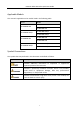
Network Video Recorder Quick Start Guide Applicable Models This manual is applicable to the models listed in the following table. Series DS-96000NI-I16 DS-96000NI-I16/H DS-96000NI-I24 DS-96000NI-I24/H Model DS-96128NI-I16 DS-96256NI-I16 DS-96128NI-I16/H DS-96256NI-I16/H DS-96128NI-I24 DS-96256NI-I24 DS-96128NI-I24/H DS-96256NI-I24/H Symbol Conventions The symbols that may be found in this document are defined as follows.
Network Video Recorder Quick Start Guide Safety Instructions ● Proper configuration of all passwords and other security settings is the responsibility of the installer and/or end-user. ● In the use of the product, you must be in strict compliance with the electrical safety regulations of the nation and region. Please refer to technical specifications for detailed information.
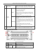
Network Video Recorder Quick Start Guide Chapter1 Panels Description 1.1 Front Panel 1.1.1 DS-96000NI-I16(/H) Series Figure 1-1 DS-96000NI-I16(/H) Series Table 1-1 Description No. Name Description 1 Locks or unlocks the panel by the key. Panel lock Returns to the previous menu. Press it twice quickly to switch the main and auxiliary Exit 2 port. In live view mode, press it to enter PTZ control Shortcut buttons interface. Press it to pop up main menu.
Network Video Recorder Quick Start Guide 4 Powers on/off device. Solid blue indicates device is powered on. Solid red indicates device is shut down. Power switch Confirms selection in any of the menu modes. Checks the checkbox fields. Switches on/off status. ENTER Plays or pauses the video playing in playback mode. Advances the video by a single frame in single-frame playback mode. Stops/starts auto switch in auto-switch mode.
Network Video Recorder Quick Start Guide HDD Solid red: at least one HDD is installed Unlit: no HDD is detected. Blinking red: HDD is reading/writing. Tx/Rx Blinking blue indicates network communication is normal. Ready Solid blue indicates device runs properly. Alarm Solid red indicates alarm occurs. 3 USB interface Universal Serial Bus (USB) ports for additional devices such as USB mouse and USB Hard Disk Drive (HDD). 4 Panel lock Locks or unlocks the panel by the key.
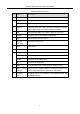
Network Video Recorder Quick Start Guide Table 1-3 Panel Description No. Name Description 1 HDMI 1/2 HDMI video output connector. 2 Audio in RCA connector for audio input. Audio out RCA connector for audio output. 3 USB 3.0 Universal Serial Bus (USB 3.0) ports for additional devices such as USB mouse and USB Hard Disk Drive (HDD). 4 LAN 4 10/100/1000 Mbps self-adaptive Ethernet interfaces. 5 eSATA Connects external SATA HDD, CD/DVD-RM. 6 VGA DB9 connector for VGA output.
Network Video Recorder Quick Start Guide Chapter 2 Installation and Connections 2.1 Installation During installation of the NVR: ● Use brackets for rack mounting. ● Ensure ample room for audio and video cables. ● When routing cables, ensure that the bend radius of the cables are no less than five times than its diameter. ● Connect the alarm cable. ● Allow at least 2cm (≈0.75-inch) of space between racks mounted devices. ● Ensure the NVR is grounded.
Network Video Recorder Quick Start Guide Figure 2-2 Insert Panel Key Step 3 Press the buttons on the panel of two sides and open the front panel. Figure 2-3 Open Panel Lock Step 4 Insert the hard disk along the slot until it is placed into position. Figure 2-4 Insert Hard Disk Step 5 Repeat the above steps to install other hard disks onto the NVR. After having finished the installation of all hard disks, close the front panel and lock it with the key again.
Network Video Recorder Quick Start Guide 2.2.2 DS-96000NI-I24(/H) Series Purpose: The following section introduces the HDD installation for the DS-96000NI-I24(/H) series NVR. Step 1 Unlock the front panel with the panel key. Figure 2-6 Unlock the Panel Step 2 To remove the cover from front panel, operate following steps: 1) Slightly pull the cover out of the device along the direction arrow ① and make it a little above the left handle. The angle between the cover and the front panel must be within 10°.
Network Video Recorder Quick Start Guide Figure 2-8 Pull out Slot Step 4 Fix the hard disk in the hard disk box. 1) Place a hard disk in the hard disk box. The SATA interface must face the hard disk box bottom. 2) Adjust the hard disk position. Ensure the hard disk rear aligning with hard disk bottom. 3) Use a screwdriver to fasten the four screws into the screw holes that in both sides. Figure 2-9 Fix the Hard Disk Step 5 Push the hard disk box back into the slot.
Network Video Recorder Quick Start Guide Figure 2-11 Press the Handle Step 7 Install the cover back to front panel. And lock it with panel key. Figure 2-12 Reinstall the Cover and Lock the Panel 2.3 Connections 2.3.1 Alarm Input Wiring The alarm input is an open/closed relay. To connect the alarm input to the device, use the following diagram. If the alarm input is not an open/close relay, please connect an external relay between the alarm input and the device.
Network Video Recorder Quick Start Guide Figure 2-13 Alarm Input Wiring 2.3.2 Alarm Output Wiring To connect to an alarm output (AC or DC load), use the following diagram: Figure 2-14 Alarm Output Wiring For DC load, the jumpers can be used within the limit of 12V/1A safely. To connect an AC load, jumpers should be left open (you must remove the jumper on the motherboard in the NVR). Use an external relay for safety (as shown in the figure above).
Network Video Recorder Quick Start Guide 2.3.4 Controller Connection Figure 2-15 Controller Connection To connect a controller to the NVR: Step 1 Disconnect pluggable block from the KB terminal block. Step 2 Unfasten stop screws from the KB D+, D- pluggable block, insert signal cables into slots and fasten stop screws. Ensure signal cables are tightly connected. Step 3 Connect Ta on controller to D+ on terminal block and Tb on controller to D- on terminal block. Fasten stop screws.
Network Video Recorder Quick Start Guide 2.4 HDD Storage Calculation Chart The following chart shows an estimation of storage space used based on recording at one channel for an hour at a fixed bit rate. Bit Rate Storage Used 96K 42M 128K 56M 160K 70M 192K 84M 224K 98M 256K 112M 320K 140M 384K 168M 448K 196M 512K 225M 640K 281M 768K 337M 896K 393M 1024K 450M 1280K 562M 1536K 675M 1792K 787M 2048K 900M 4096K 1.8G 8192K 3.6G 16384K 7.
Network Video Recorder Quick Start Guide Chapter 3 Menu Operation 3.1 Start up Your Device Proper startup and shutdown procedures are crucial to expanding the life of the NVR. To start your device: Step 1 Check the power supply is plugged into an electrical outlet. It is HIGHLY recommended that an Uninterruptible Power Supply (UPS) be used in conjunction with the device. The Power button on the front panel should be red, indicating the device is receiving the power.
Network Video Recorder Quick Start Guide Figure 3-1 Setting Admin Password We highly recommend you create a strong password of your own choosing (Using a minimum of 8 characters, including at least three of the following categories: upper case letters, lower case letters, numbers, and special characters.) in order to increase the security of your product.
Network Video Recorder Quick Start Guide Step 1 After the device is activated, you can enter the following interface to configure the device unlock pattern. Step 2 Use the mouse to draw a pattern among the 9 dots on the screen. Release the mouse when the pattern is done. Figure 3-2 Draw the Pattern Connect at least 4 dots to draw the pattern. Each dot can be connected for once only. Step 3 Draw the same pattern again to confirm it. When the two patterns match, the pattern is configured successfully. 3.
Network Video Recorder Quick Start Guide Figure 3-3 Login Interface Step 3 Input Password. Step 4 Click Login. In the Login dialog box, if you enter the wrong password 7 times, the current user account will be locked for 60 seconds. 3.5 Enter Wizard to Configure Fast Basic Settings The Setup Wizard can walk you through some important settings of the device. By default, the Setup Wizard starts once the device has loaded. Check the checkbox to enable Setup Wizard when device starts.
Network Video Recorder Quick Start Guide 3.6 Network Settings Purpose: Network settings must be properly configured before you operate device over network. Step 1 Go to System > Network > TCP/IP. Figure 3-5 Network Settings Step 2 Select the General tab. Step 3 In the General Settings interface, you can configure the following settings: NIC Type, IPv4 Address, IPv4 Gateway, MTU and DNS Server.
Network Video Recorder Quick Start Guide Step 1 Click on the main menu bar to enter the Camera Management. Step 2 Click the Custom Add tab on the title bar to enter the Add IP Camera interface. Figure 3-6 Add IP Camera Step 3 Enter IP address, protocol, management port, and other information of the IP camera to add. Step 4 Enter the login user name and password of the IP camera. Step 5 Click Add to finish the adding of the IP camera.
Network Video Recorder Quick Start Guide The device supports the RAID storage function. Through one-touch configuration, you can quickly create the disk array. By default, the array type to be created is RAID 5. Before you start: ● Enable RAID function. ● Install at least 3 HDDs. If more than 10 HDDs are installed, 2 arrays will be created. To maintain reliable and stable running of the HDDs, it is recommended to use enterprise-level HDDs with the same model and capacity.
Network Video Recorder Quick Start Guide Step 3 Check the Enable Schedule. Step 4 Select a Record Type. The record type can be Continuous, Motion Detection, Alarm, Motion | Alarm, Motion & Alarm, Event, etc. Figure 3-8 Record Schedule Step 5 Select a day and click-and-drag the mouse on the time bar to set the record schedule. Step 6 Click Apply to save the settings. 3.
Network Video Recorder Quick Start Guide Figure 3-9 Playback Interface 26
Network Video Recorder Quick Start Guide Chapter 4 Access by Web Browser You shall acknowledge that the use of the product with Internet access might be under network security risks. For avoidance of any network attacks and information leakage, please strengthen your own protection. If the product does not work properly, please contact with your dealer or the nearest service center. Purpose: You can get access to the device via web browser.
Network Video Recorder Quick Start Guide ● If the device is already activated, enter the user name and password in the login interface, and click the Login button. Figure 4-2 Login Step 3 Install the plug-in before viewing the live video and managing the camera. Please follow the installation prompts to install the plug-in. You may have to close the web browser to finish the installation of the plug-in.
UD07826N