
User Manual
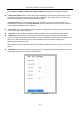
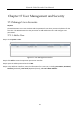

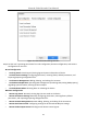
Table Of Contents
- Introduction
- Chapter 2 Getting Started
- Chapter 3 Camera Management
- Chapter 4 Camera Settings
- Chapter 5 Live View
- Chapter 6 PTZ Control
- Chapter 7 Storage
- 7.1 Storage Device Management
- 7.2 Storage Mode
- 7.3 Recording Parameters
- 7.4 Configure Recording Schedule
- 7.5 Configure Continuous Recording
- 7.6 Configure Motion Detection Triggered Recording
- 7.7 Configure Event Triggered Recording
- 7.8 Configure Alarm Triggered Recording
- 7.9 Configure POS Event Triggered Recording
- 7.10 Configure Picture Capture
- 7.11 Configure Holiday Recording and Capture
- 7.12 Configure Redundant Recording and Capture
- Chapter 8 Disk Array (RAID)
- Chapter 9 File Management
- Chapter 10 Playback
- Chapter 11 Event and Alarm Settings
- 11.1 Configure Arming Schedule
- 11.2 Configure Alarm Linkage Actions
- 11.3 Configure Motion Detection Alarms
- 11.4 Configure Video Loss Alarms
- 11.5 Configure Video Tampering Alarms
- 11.6 Configure Sensor Alarms
- 11.7 Configure Exceptions Alarms
- 11.8 Setting Alarm Linkage Actions
- 11.9 Trigger or Clear Alarm Output Manually
- Chapter 12 VCA Event Alarm
- 12.1 Face Detection
- 12.2 Vehicle Detection
- 12.3 Line Crossing Detection
- 12.4 Intrusion Detection
- 12.5 Region Entrance Detection
- 12.6 Region Exiting Detection
- 12.7 Unattended Baggage Detection
- 12.8 Object Removal Detection
- 12.9 Audio Exception Detection
- 12.10 Sudden Scene Change Detection
- 12.11 Defocus Detection
- 12.12 PIR Alarm
- 12.13 Thermal Camera Detection
- Chapter 13 Smart Analysis
- Chapter 14 POS Configuration
- Chapter 15 Network Settings
- Chapter 16 Hot Spare Device Backup
- Chapter 17 User Management and Security
- Chapter 18 System Service Maintenance
- Chapter 19 General System Settings
- Chapter 20 Appendix

Network Video Recorder User Manual
160
Go to System > Network > Advanced > More Settings and configure port settings as needed.
Alarm Host IP/Port: With a remote alarm host configured, the device will send the alarm event
or exception message to the host when an alarm is triggered. The remote alarm host must have
the client management system (CMS) software installed.
The Alarm Host IP refers to the IP address of the remote PC on which the CMS software (e.g.,
iVMS-4200) is installed, and the Alarm Host Port (7200 by default) must be the same as the alarm
monitoring port configured in the software.
Server Port: Server port (8000 by default) should be configured for remote client software access
and its valid range is 2000 to 65535.
HTTP Port: HTTP port (80 by default) should be configured for remote Web browser access.
Multicast IP: Multicast can be configured to enable Live View for cameras that exceed the
maximum number allowed through network. A multicast IP address covers Class-D IP ranging from
224.0.0.0 to 239.255.255.255 and it is recommended to use an IP address ranging from
239.252.0.0 to 239.255.255.255.
When adding a device to the CMS software, the multicast address must be the same as that of the
device.
RTSP Port: RTSP (Real Time Streaming Protocol) is a network control protocol designed to control
streaming media servers. The port is 554 by default.
Figure 15-12 Port Settings