
User Manual
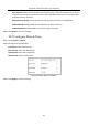
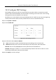
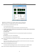
Table Of Contents
- Introduction
- Chapter 2 Getting Started
- Chapter 3 Camera Management
- Chapter 4 Camera Settings
- Chapter 5 Live View
- Chapter 6 PTZ Control
- Chapter 7 Storage
- 7.1 Storage Device Management
- 7.2 Storage Mode
- 7.3 Recording Parameters
- 7.4 Configure Recording Schedule
- 7.5 Configure Continuous Recording
- 7.6 Configure Motion Detection Triggered Recording
- 7.7 Configure Event Triggered Recording
- 7.8 Configure Alarm Triggered Recording
- 7.9 Configure POS Event Triggered Recording
- 7.10 Configure Picture Capture
- 7.11 Configure Holiday Recording and Capture
- 7.12 Configure Redundant Recording and Capture
- Chapter 8 Disk Array (RAID)
- Chapter 9 File Management
- Chapter 10 Playback
- Chapter 11 Event and Alarm Settings
- 11.1 Configure Arming Schedule
- 11.2 Configure Alarm Linkage Actions
- 11.3 Configure Motion Detection Alarms
- 11.4 Configure Video Loss Alarms
- 11.5 Configure Video Tampering Alarms
- 11.6 Configure Sensor Alarms
- 11.7 Configure Exceptions Alarms
- 11.8 Setting Alarm Linkage Actions
- 11.9 Trigger or Clear Alarm Output Manually
- Chapter 12 VCA Event Alarm
- 12.1 Face Detection
- 12.2 Vehicle Detection
- 12.3 Line Crossing Detection
- 12.4 Intrusion Detection
- 12.5 Region Entrance Detection
- 12.6 Region Exiting Detection
- 12.7 Unattended Baggage Detection
- 12.8 Object Removal Detection
- 12.9 Audio Exception Detection
- 12.10 Sudden Scene Change Detection
- 12.11 Defocus Detection
- 12.12 PIR Alarm
- 12.13 Thermal Camera Detection
- Chapter 13 Smart Analysis
- Chapter 14 POS Configuration
- Chapter 15 Network Settings
- Chapter 16 Hot Spare Device Backup
- Chapter 17 User Management and Security
- Chapter 18 System Service Maintenance
- Chapter 19 General System Settings
- Chapter 20 Appendix

Network Video Recorder User Manual
196
If it is solved, finish the process.
If not, please contact the engineer from Hikvision to do the further process.
The IP camera frequently goes online and offline and the status of it displays as
“Disconnected”.
Possible Reasons:
− The IP camera and the device versions are not compatible.
− Unstable power supply of IP camera.
− Unstable network between IP camera and device.
− Limited flow by the switch connected with IP camera and device.
Step 1 Verify the IP camera and the device versions are compatible.
1) Go to Menu>Camera, and view the firmware version of connected IP camera.
2) Go to Menu>Maintenance>System Info>Device Info and view the firmware version of device.
Step 2 Verify power supply of IP camera is stable.
1) Verify the power indicator is normal.
2) When the IP camera is offline, please try the ping command on PC to check if the PC connects
with the IP camera.
Step 3 Verify the network between IP camera and device is stable.
3) When the IP camera is offline, connect PC and device with the RS-232 cable.
4) Open the Super Terminal, use the ping command and keep sending large data packages to the
connected IP camera, and check if there exists packet loss.
Simultaneously press Ctrl and C to exit the ping command.
Example: Input ping 172.6.22.131 –l 1472 –f.
Step 1 Verify the switch is not flow control.
Check the brand, model of the switch connecting IP camera and device, and contact with the
manufacturer of the switch to check if it has the function of flow control. If so, please turn it
down.
Step 2 Check if the fault is solved by the step 1 to step 4.
If it is solved, finish the process.
If not, please contact the engineer from Hikvision to do the further process.
No monitor connected with the device locally and when you manage the IP camera to connect
with the device by web browser remotely, of which the status displays as Connected. And then