
User Manual
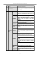
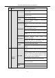
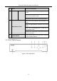
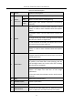
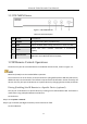
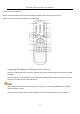
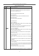
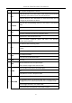
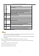
Table Of Contents
- Introduction
- Chapter 2 Getting Started
- Chapter 3 Camera Management
- Chapter 4 Camera Settings
- Chapter 5 Live View
- Chapter 6 PTZ Control
- Chapter 7 Storage
- 7.1 Storage Device Management
- 7.2 Storage Mode
- 7.3 Recording Parameters
- 7.4 Configure Recording Schedule
- 7.5 Configure Continuous Recording
- 7.6 Configure Motion Detection Triggered Recording
- 7.7 Configure Event Triggered Recording
- 7.8 Configure Alarm Triggered Recording
- 7.9 Configure POS Event Triggered Recording
- 7.10 Configure Picture Capture
- 7.11 Configure Holiday Recording and Capture
- 7.12 Configure Redundant Recording and Capture
- Chapter 8 Disk Array (RAID)
- Chapter 9 File Management
- Chapter 10 Playback
- Chapter 11 Event and Alarm Settings
- 11.1 Configure Arming Schedule
- 11.2 Configure Alarm Linkage Actions
- 11.3 Configure Motion Detection Alarms
- 11.4 Configure Video Loss Alarms
- 11.5 Configure Video Tampering Alarms
- 11.6 Configure Sensor Alarms
- 11.7 Configure Exceptions Alarms
- 11.8 Setting Alarm Linkage Actions
- 11.9 Trigger or Clear Alarm Output Manually
- Chapter 12 VCA Event Alarm
- 12.1 Face Detection
- 12.2 Vehicle Detection
- 12.3 Line Crossing Detection
- 12.4 Intrusion Detection
- 12.5 Region Entrance Detection
- 12.6 Region Exiting Detection
- 12.7 Unattended Baggage Detection
- 12.8 Object Removal Detection
- 12.9 Audio Exception Detection
- 12.10 Sudden Scene Change Detection
- 12.11 Defocus Detection
- 12.12 PIR Alarm
- 12.13 Thermal Camera Detection
- Chapter 13 Smart Analysis
- Chapter 14 POS Configuration
- Chapter 15 Network Settings
- Chapter 16 Hot Spare Device Backup
- Chapter 17 User Management and Security
- Chapter 18 System Service Maintenance
- Chapter 19 General System Settings
- Chapter 20 Appendix

Network Video Recorder User Manual
24
1.1.3 DS-7600NI Series
Figure 1-4 DS-7600NI Series
Table 1-3 Panel Description
1.2 IR Remote Control Operations
The device may also be controlled with the included IR remote control, shown in Figure 1-5.
Batteries (2×AAA) must be installed before operation.
The IR remote is set at the factory to control the device (using default Device ID# 255) without any
additional steps. Device ID# 255 is the default universal device identification number shared by the
devices. You may also pair an IR Remote to a specific device by changing the Device ID#, as follows:
Pairing (Enabling) the IR Remote to a Specific Device (optional)
You can pair an IR Remote to a specific device by creating a user-defined Device ID#. This feature is
useful when using multiple IR Remotes and devices.
On the device:
Step 1 Go to System > General.
Step 2 Type a number (255 digits maximum) into the Device No. field.
On the IR Remote:
No.
Name
Connections
1
POWER
Turns green when device is powered up.
2
HDD
Flickers red when data is being read from or written to HDD.
3
Tx/Rx
Flickers blue when network connection is functioning
properly.
4
USB Interface
Universal Serial Bus (USB) port for additional devices such as
USB mouse and USB Hard Disk Drive (HDD).