
User Manual
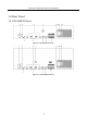
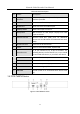
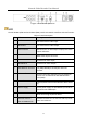
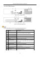
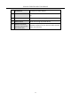
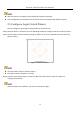
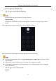
Table Of Contents
- Introduction
- Chapter 2 Getting Started
- Chapter 3 Camera Management
- Chapter 4 Camera Settings
- Chapter 5 Live View
- Chapter 6 PTZ Control
- Chapter 7 Storage
- 7.1 Storage Device Management
- 7.2 Storage Mode
- 7.3 Recording Parameters
- 7.4 Configure Recording Schedule
- 7.5 Configure Continuous Recording
- 7.6 Configure Motion Detection Triggered Recording
- 7.7 Configure Event Triggered Recording
- 7.8 Configure Alarm Triggered Recording
- 7.9 Configure POS Event Triggered Recording
- 7.10 Configure Picture Capture
- 7.11 Configure Holiday Recording and Capture
- 7.12 Configure Redundant Recording and Capture
- Chapter 8 Disk Array (RAID)
- Chapter 9 File Management
- Chapter 10 Playback
- Chapter 11 Event and Alarm Settings
- 11.1 Configure Arming Schedule
- 11.2 Configure Alarm Linkage Actions
- 11.3 Configure Motion Detection Alarms
- 11.4 Configure Video Loss Alarms
- 11.5 Configure Video Tampering Alarms
- 11.6 Configure Sensor Alarms
- 11.7 Configure Exceptions Alarms
- 11.8 Setting Alarm Linkage Actions
- 11.9 Trigger or Clear Alarm Output Manually
- Chapter 12 VCA Event Alarm
- 12.1 Face Detection
- 12.2 Vehicle Detection
- 12.3 Line Crossing Detection
- 12.4 Intrusion Detection
- 12.5 Region Entrance Detection
- 12.6 Region Exiting Detection
- 12.7 Unattended Baggage Detection
- 12.8 Object Removal Detection
- 12.9 Audio Exception Detection
- 12.10 Sudden Scene Change Detection
- 12.11 Defocus Detection
- 12.12 PIR Alarm
- 12.13 Thermal Camera Detection
- Chapter 13 Smart Analysis
- Chapter 14 POS Configuration
- Chapter 15 Network Settings
- Chapter 16 Hot Spare Device Backup
- Chapter 17 User Management and Security
- Chapter 18 System Service Maintenance
- Chapter 19 General System Settings
- Chapter 20 Appendix

Network Video Recorder User Manual
32
Table 1-6 Panel Description
No.
Name
Description
1
LAN1/LAN2
Interface
2 RJ-45 10/100/1000 Mbps self-adaptive Ethernet
interfaces provided.
2
LINE IN
RCA connector for audio input.
3
AUDIO OUT
2 RCA connectors for audio output.
4
HDMI1/HDMI2
HDMI video output connector.
5
VGA1/VGA2
DB9 connector for VGA output. Display local video
output and menu.
6
USB 3.0 interface
Universal Serial Bus (USB) ports for additional
devices such as USB mouse and USB Hard Disk Drive
(HDD).
7
RS-232 Interface
Connector for RS-232 devices.
8
eSATA
Connects external SATA HDD, CD/DVD-RM.
9
Controller Port
D+, D- pin connects to Ta, Tb pin of controller. For
cascading devices, the first device’s D+, D- pin should
be connected with the D+, D- pin of the next device.
ALARM IN
Connector for alarm input.
ALARM OUT
Connector for alarm output.
10
100 to 240 VAC
100 to 240 VAC power supply.
11
Power Switch
Switch for turning on/off the device.
12
GROUND
Ground (needs to be connected when device starts
up).
1.4.2 DS-7600NI Series
Figure 1-8 DS-7600NI-I2 Series