
User Manual
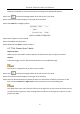
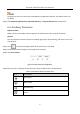
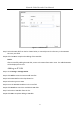
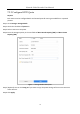
Table Of Contents
- Introduction
- Chapter 2 Getting Started
- Chapter 3 Camera Management
- Chapter 4 Camera Settings
- Chapter 5 Live View
- Chapter 6 PTZ Control
- Chapter 7 Storage
- 7.1 Storage Device Management
- 7.2 Storage Mode
- 7.3 Recording Parameters
- 7.4 Configure Recording Schedule
- 7.5 Configure Continuous Recording
- 7.6 Configure Motion Detection Triggered Recording
- 7.7 Configure Event Triggered Recording
- 7.8 Configure Alarm Triggered Recording
- 7.9 Configure POS Event Triggered Recording
- 7.10 Configure Picture Capture
- 7.11 Configure Holiday Recording and Capture
- 7.12 Configure Redundant Recording and Capture
- Chapter 8 Disk Array (RAID)
- Chapter 9 File Management
- Chapter 10 Playback
- Chapter 11 Event and Alarm Settings
- 11.1 Configure Arming Schedule
- 11.2 Configure Alarm Linkage Actions
- 11.3 Configure Motion Detection Alarms
- 11.4 Configure Video Loss Alarms
- 11.5 Configure Video Tampering Alarms
- 11.6 Configure Sensor Alarms
- 11.7 Configure Exceptions Alarms
- 11.8 Setting Alarm Linkage Actions
- 11.9 Trigger or Clear Alarm Output Manually
- Chapter 12 VCA Event Alarm
- 12.1 Face Detection
- 12.2 Vehicle Detection
- 12.3 Line Crossing Detection
- 12.4 Intrusion Detection
- 12.5 Region Entrance Detection
- 12.6 Region Exiting Detection
- 12.7 Unattended Baggage Detection
- 12.8 Object Removal Detection
- 12.9 Audio Exception Detection
- 12.10 Sudden Scene Change Detection
- 12.11 Defocus Detection
- 12.12 PIR Alarm
- 12.13 Thermal Camera Detection
- Chapter 13 Smart Analysis
- Chapter 14 POS Configuration
- Chapter 15 Network Settings
- Chapter 16 Hot Spare Device Backup
- Chapter 17 User Management and Security
- Chapter 18 System Service Maintenance
- Chapter 19 General System Settings
- Chapter 20 Appendix

Network Video Recorder User Manual
72
The park time can be set only via the speed dome configuration interface. The default value is 5s
by default.
Step 3 Click Stop Park (Quick Patrol), Stop Park (Patrol 1), or Stop Park (Preset 1) to inactivate it.
6.4 Auxiliary Functions
Before You Start
Make sure the connected IP camera supports the PTZ function and is properly connected.
Purpose
You can operate the auxiliary functions including light, wiper, 3D positioning, and center on the PTZ
control panel.
Step 1 Click on the quick settings toolbar of the PTZ camera’s Live View.
Step 2 The PTZ control panel displays on the right of the interface.
Step 3 Click Aux Function.
Figure 6-14 Aux Function Configuration
Step 4 Click the icons to operate the aux functions. See the table for the icon descriptions.
Table 6-1 Description of Aux Functions Icons
Icon
Description
Light on/off
Wiper on/off
3D positioning
Center