DS-K1106 Series Card Reader Installation Manual UD.
User Manual COPYRIGHT © 2015 Hangzhou Hikvision Digital Technology Co., Ltd. ALL RIGHTS RESERVED. Any and all information, including, among others, wordings, pictures, graphs are the properties of Hangzhou Hikvision Digital Technology Co., Ltd. or its subsidiaries (hereinafter referred to be “Hikvision”). This user manual (hereinafter referred to be “the Manual”) cannot be reproduced, changed, translated, or distributed, partially or wholly, by any means, without the prior written permission of Hikvision.
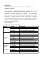
Series DS-K11046 Series Models DS-K1104CK Description CPU card reader (with a keypad) DS-K1106M MIFARE card reader(without keypad) DS-K1106C CPU card reader (without keypad) DS-K1106S ID card reader (without keypad) The Manual includes instructions for using and managing the product. Pictures, charts, images and all other information hereinafter are for description and explanation only.
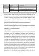
PRODUCT SHALL BE WHOLLY AT YOUR OWN RISKS. HIKVISION SHALL NOT TAKE ANY RESPONSIBILITES FOR ABNORMAL OPERATION, PRIVACY LEAKAGE OR OTHER DAMAGES RESULTING FROM CYBER ATTACK, HACKER ATTACK, VIRUS INSPECTION, OR OTHER INTERNET SECURITY RISKS; HOWEVER, HIKVISION WILL PROVIDE TIMELY TECHNICAL SUPPORT IF REQUIRED. SURVEILLANCE LAWS VARY BY JURISDICTION. PLEASE CHECK ALL RELEVANT LAWS IN YOUR JURISDICTION BEFORE USING THIS PRODUCT IN ORDER TO ENSURE THAT YOUR USE CONFORMS THE APPLICABLE LAW.
Content CHAPTER 1 PREVENTIVE AND CAUTIONARY TIPS ................... 2 CHAPTER 2 INTRODUCTION ................................................... 3 2.1 2.2 2.3 CHAPTER 3 3.1 3.2 3.3 3.4 3.5 CHAPTER 4 FRONT VIEW ................................................................. 3 REAR VIEW ................................................................... 4 SIDE VIEW ..................................... 错误!未定义书签。 INSTALLATION .....................................................
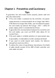
Chapter 1 Preventive and Cautionary Tips To guarantee the card reader works properly, please read and obey the notes below. If the card reader is powered by the controller, the power supply distance is recommended to be no longer than 100m. If the distance is longer than 100m, you are advised to power the card reader by external 12V (range: -%10 ~ +%10) DC power supply, which is nonswitched and linear.
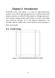
Chapter 2 Introduction DS-K1106 series card reader is a kind of high-performance product, with a 32 bit high-speed processor. It communicates with access controller via either RS-485 protocol or Wiegand protocol. And a build-in tamper-proof module helps to protect card reader from malicious damage. As to the physical appearance, the PC+ABS material makes water proof and dust proof possible in poor environment. 2.
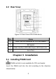
2.2 Rear View Figure 2-2 Rear View of DS-K1106 Series No. Name 1 PSAM Card Slot (available for CPU card reader) 2 DIP Switch 3 Cable Interface of RS-485, Power, LED Control, etc. 4 Serial Port Chapter 3 Installation 3.1 Installing PSAM Card PSAM card slot is only available for CPU card reader. Insert the PSAM card into the slot according to the direction shown below.
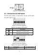
Figure 3-1 PSAM Card Slot 3.2 Introduction for DIP Switch The DIP switch module is shown below. The No. of DIP switch from left to right is 1 ~ 8. Figure 3-2 DIP Switch Module Table 3-1 Description of DIP Switch Icon Description Represent 1 in binary mode Represent 0 in binary mode For example, binary value of the following status is: 0000 1100. Figure 3-3 DIP Switch Module Table 3-2 Description of DIP Switch No.
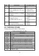
No. Description DIP Switch Status 0: 0 Read card No. or file in card. (Only available for CPU card reader.) Wiegand protocol or RS-485 protocol. 5 6 7 Wiegand Protocol (available when No. 6 is 1) 8 Matched Resistance (available for RS-485 protocol) 1: read card No; 0: read file in card. 1: Wiegand protocol; 0: RS-485 protocol. 1: Wiegand protocol of 26-bit; 0: Wiegand protocol of 34-bit. 1: Enable; 0: Disable. 3.3 Definition of Cable The description of 10 cables is shown below.
3.4 Wiring Cables Purpose: Wire the cables between controller and card reader, thus to establish the communication between them. Steps for RS-485 communication mode: 1. Set the DIP switch of No. 6 as 0. 2. Set the DIP switch of No. 1 ~ 5 for RS-485 address and reading card mode. For details, please refer to 3.2 Introduction for DIP Switch. 3. Wire the cable between controller and card reader as shown below.
Black Red Black Blue Yellow Controller Card Reader Figure 3-4 Wiring for RS-485 Communication Mode Steps for Wiegand communication mode: 1. Set the DIP switch of No. 6 as 1. 2. Set the DIP switch of No. 5 and 7 for reading card mode and Wiegand protocol. For details, please refer to 3.2 Introduction for DIP Switch. 3. Wiring the cable between controller and card reader as shown below.
Brown Purple Orange White Red Green Black Controller Card Reader Figure 3-5 Wiring for Wiegand Communication Mode 3.5 Installing Card Reader Before you start: Set the DIP switch. For details, refer to 3.2 Introduction for DIP Switch.
Installation for DS-K1101/ 02/ 03/ 04 series card reader Steps: 1. Fix the gang box on the wall or other place. 2. 3. 4. 5. Connect the cables between controller and card reader. For details, refer to 3.4 Wiring Cables. Push the card reader to match the fixed gang box. Fasten the screw to keep the components together. Fix the side cover onto the card reader, press the cover to make it tightly fit the reader.
starting up process is completed. During using the card reader, it will send out different sounds prompt and the LED indicator on it have different statuses. You can refer to tables below for detailed information. Table 4-1 Description of Prompt Sound Sound Prompt Description RS-485 protocol: Pressing keys prompt; Swiping card prompt; Time out prompt for One beep pressing keys or swiping card. Wiegand protocol: Pressing keys prompt; Swiping card prompt.
LED Indicator Status Red and Keeping rapidly blinking Description Available for reading file mode of CPU card: PSAM is not inserted or undetected.
13