Access Control Terminal User Manual
Access Control Terminal·User Manual User Manual © 2017 Hangzhou Hikvision Digital Technology Co., Ltd. This manual is applied for access control terminal. Series Model DS-K1T105E/M Standalone Access Control Terminal DS-K1T105E/M-C(with Camera) DS-K1T200EF/MF DS-K1T200EF/MF-C(with Camera) Optical IP-Based Fingerprint Access Control Terminal DS-K1T201EF/MF DS-K1T201EF/MF-C(with Camera) It includes instructions on how to use the Product.
Access Control Terminal·User Manual Regulatory Information FCC Information Please take attention that changes or modification not expressly approved by the party responsible for compliance could void the user’s authority to operate the equipment. FCC compliance: This equipment has been tested and found to comply with the limits for a Class B digital device, pursuant to part 15 of the FCC Rules.
Access Control Terminal·User Manual 2006/66/EC (battery directive): This product contains a battery that cannot be disposed of as unsorted municipal waste in the European Union. See the product documentation for specific battery information. The battery is marked with this symbol, which may include lettering to indicate cadmium (Cd), lead (Pb), or mercury (Hg). For proper recycling, return the battery to your supplier or to a designated collection point. For more information see: www.recyclethis.
Access Control Terminal·User Manual or property loss. The precaution measure is divided into Warnings and Cautions: Warnings: Neglecting any of the warnings may cause serious injury or death. Cautions: Neglecting any of the cautions may cause injury or equipment damage. Warnings Follow these safeguards to prevent serious injury or death. Cautions Follow these precautions to prevent potential injury or material damage.
Access Control Terminal·User Manual Please use the provided glove when open up the device cover, avoid direct contact with the device cover, because the acidic sweat of the fingers may erode the surface coating of the device cover. Please use a soft and dry cloth when clean inside and outside surfaces of the device cover, do not use alkaline detergents. Please keep all wrappers after unpack them for future use.
Access Control Terminal·User Manual Table of Contents Chapter 1 Overview ................................................................................................................. 1 1.1 Introduction ......................................................................................................................... 1 1.2 Main Features ...................................................................................................................... 1 1.2.
Access Control Terminal·User Manual 7.1.2 Managing User ............................................................................................................... 27 7.2 Communication Settings .................................................................................................... 29 7.2.3 Network Settings ............................................................................................................ 30 7.2.4 Serial Port Settings ..............................................
Access Control Terminal·User Manual 8.6.2 Managing Person............................................................................................................ 87 8.6.3 Issuing Card in Batch ...................................................................................................... 88 8.7 Schedule and Template ...................................................................................................... 89 8.7.1 Week Schedule .......................................................
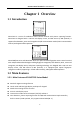
Access Control Terminal·User Manual Chapter 1 Overview 1.1 Introduction DS-K1T105 is a series of standalone access control terminal with picture capturing function. DS-K1T105 is designed with a 2.8-inch LCD display screen, and HD camera (2 MP optional). It supports face detection, smart card recognition TCP/IP communication method, Wi-Fi communication method, and supports offline operation.
Access Control Terminal·User Manual Supports multiple door opening modes (card, card + password, exit button, etc.) Supports RS-485 communication for connecting to external card reader Supports working as a card reader, and supports Wiegand interface and RS-485 interface for accessing the controller Max. 100,000 valid card No., and Max. 300,000 access control events records storage Supports EM card reading (DS-K1T105E/E-C) Supports Mifare card reading, including card No.
Access Control Terminal·User Manual Accurate data and time display provided by built-in electronic clock and watchdog program to ensure the basic function of the terminal Data can be permanently saved after power-off.
Access Control Terminal·User Manual Chapter 2 Appearance 2.1 Appearance of DS-K1T105 Series Model Please refer to the following content for detailed information of the DS-K1T105 series model. Table 1-1 Description of DS-K1T105 Series Model No. Description 1 HD Camera with 2 MP (only DS-K1T105E/M/ -C support) 2 2.8-Inch LCD Display Screen 3 Keypad 4 USB 2.0 Interface 5 PSAM Card Slot 6 Power Interface 7 External Wiring Terminals 8 Ethernet Port 9 Tampering Prevention Switch 2.
Access Control Terminal·User Manual Table 1-2 DS-K1T200/201 Series Fingerprint Access Control Terminal Components No. Description HD Camera with 2 MP (only 1 DS-K1T200EF/MF -C support) 2 2.8-Inch LCD Display Screen 3 Keypad Optical Fingerprint Reading Module USB 2.0 Interface PSAM Card Slot Power Interface External Wiring Terminals Ethernet Port Tampering Prevention Switch 4 5 6 7 8 9 10 2.
Access Control Terminal·User Manual No. 1 2 3 4 5 6 Table 1-3 Description of Keys Description Editing Key: Click the key to enter/exit the editing status. Numeric Keys: Enter number in the textbox. Direction Keys: Select icons in the menu. Exiting Key: Click the key to exit the menu. Confirming Key: Click the key to confirm operations. Long-press the key to enter the login interface. Deleting Key: Click the key to delete contents in the textbox. Solid Blue: Normal Power.
Access Control Terminal·User Manual Chapter 3 Installation Note: Make sure that the wall is strong enough to withstand three times the weight of the device. 3.1 Installation of DS-K1T105 Series Device Steps: 1. Install the 86 gang box into the wall. 2. Secure the device mounting plate on the gang box with two srews (supplied). 3. Align the terminal with mounting plate. 4. Buckle the terminal on the plate. 5. Tigten the srew to fix the terminal on the mounting plate and complete the installation.
Access Control Terminal·User Manual 3.2 Installation of DS-K1T200/201 Series Device Steps: 1. Install the 86 gang box into the wall. 2. Secure the device mounting plate on the gang box with two srews (supplied). 3. Align the terminal with mounting plate. 4. Buckle the terminal on the plate.
Access Control Terminal·User Manual 5. Tigten the srews to fix the terminal on the mounting plate and complete the installation.
Access Control Terminal·User Manual Chapter 4 Terminal Connection 10
Access Control Terminal·User Manual Line Group Line Group A No.
Access Control Terminal·User Manual Line Group No.
Access Control Terminal·User Manual Chapter 5 Wiring Description 5.
Access Control Terminal·User Manual 5.2 The Wiring of External Card Reader 5.2.1 The Wiring of External RS-485 Card Reader 5.2.2 The Wiring of External Wiegand Card Reader Notes: Set the dial-up of the external card reader as 2 when connected to the access control terminal. The external power supply and the access control terminal should use the same GND cable.
Access Control Terminal·User Manual 5.3 The Wiring of Electric Lock and Door Contact 5.3.1 The Wiring of Electric Lock Note: Signal input interface of the door status (DOOR_NC, DOOR_COM, DOOR_NO) is used to recognize whether the door is locked. If the NC interface is connected for opening door, the NO interface can only be connected for locking door. 5.3.
Access Control Terminal·User Manual 5.4 The Wiring of Exit Button 5.
Access Control Terminal·User Manual 5.6 The Wiring of External Alarm Device 5.7 Card Reader Connection The access control terminal can be switched into the card reader mode. It can access to the access control as a card reader, and supports Wiegand communication port and RS-485 communication port. Note: When the access control terminal works as a card reader, it only supports being connected to the controller, but does not support alarm input or output, or the connection of external devices. 5.7.
Access Control Terminal·User Manual Notes: When the access control terminal works as a card reader, you must connect the WG_ERR, BUZZER and WG_OK terminals if you want to control the LED and buzzer of the Wiegand card reader. Set the working mode of the terminal as card reader, which can be configured in System Parameter –> Mode Switch, if the terminal is required to work as a card reader. The card reader mode support to communicate by Wiegand or RS-485.
Access Control Terminal·User Manual Chapter 6 Activating Access Control Terminal Purpose: You are required to activate the terminal first before using it. Activation via SADP, and Activation via client software are supported. The default values of the control terminal are as follows. The default IP address: 192.0.0.64. The default port No.: 8000. The default user name: admin. 6.1 Activating via Device If the device is not activated, you can activate the device after it is powering on. Steps: 1.
Access Control Terminal·User Manual 3. Move the cursor to # Activate and tap the # key to active the device. STRONG PASSWORD RECOMMENDED– We highly recommend you create a strong password of your own choosing (using a minimum of 8 characters, including upper case letters, lower case letters, numbers, and special characters) in order to increase the security of your product.
Access Control Terminal·User Manual segment with your computer by either modifying the IP address manually or checking the checkbox of Enable DHCP. 6. Input the password and click the Modify button to activate your IP address modification. 6.3 Activating via Client Software The client software is versatile video management software for multiple kinds of devices. Get the client software from the supplied disk or the official website, and install the software according to the prompts.
Access Control Terminal·User Manual 2. Click Device Management to enter the Device Management interface. 3. Check the device status from the device list, and select an inactive device. 4. Check the device status from the device list, and select an inactive device. 5. Click the Activate button to pop up the Activation interface 6. In the pop-up window, create a password in the password field, and confirm the password.
Access Control Terminal·User Manual 7. Click OK button to start activation. 8. Click the Modify Netinfor button to pop up the Network Parameter Modification interface. 9. Change the device IP address to the same network segment with your computer by either modifying the IP address manually. 10. Input the password and click the OK button to save the settings.
Access Control Terminal·User Manual Chapter 7 Basic Operation Before You Start: You should activate the device before the first login. Otherwise, after powered on, the system will switch into the Device Activation interface. For detailed information about activation, see Chapter 6 Activating Access Control Terminal. The working flow is as follows: Steps: 1. Power on the device to enter the initial interface. 2. Long-tap the # key for 3s to enter the password authentication interface. 3.
Access Control Terminal·User Manual 1) Tap the key (Edit key) to enter the editing mode. 2) Tap F1 key to switch the input method. 3) Enter the (activation) password into the textbox. 4) Tap the key to exit the editing mode. 4. Tap the # key to confirm the settings. The system will enter the menu operation interface. On the menu operation interface, you can manage users, set communication parameters, set system parameters, and so on.
Access Control Terminal·User Manual In the Adding User menu, you can add users, register card, and record fingerprints optionally for the corresponding person. Steps: 1. Use the Up, Down, Left, Right key to move the cursor to Add (add user) by using the direction keys. 2. Tap the # key to enter the Add interface. 3. Register the card. Register the card by swiping the card. 1) Place the card on the induction area. 2) The system displays the card No.
Access Control Terminal·User Manual 2) Place the finger on the fingerprint scanner, rise and rest your finger by following the corresponding voice prompts. Notes: The fingerprint registration function only supports device with fingerprint module. The same fingerprint cannot be repeatedly registered. For the optical access control terminal, you should place your finger twice to register the fingerprint. For details about scanning fingerprints, refer to Appendix. 7.1.
Access Control Terminal·User Manual 5. Input the card number to Input Card No. textbox. 6. Tap the # key to view the basic information about the card holder. Editing User Steps: 1. Move the cursor to a user by using the direction keys. 2. Tap the # key to pop up an interface for selecting corresponding operations. 3. Move the cursor to Edit User. 4. Tap the # key to enter the editing interface. 5. Edit the user information. Adding the Fingerprint.
Access Control Terminal·User Manual Changing the valid date. You can set the start/end time of the user’s permission. Tap the key to enter/exit the editing mode. Enabling first card Tap the # key to enable first card. Note: After enabling first card, the door remains open during the pre-defined valid duration. 6. Move the cursor to the OK button, and tap the # key to confirm the settings. Deleting User Steps: 1. Move the cursor to a user by using direction keys. 2.
Access Control Terminal·User Manual Network Settings: Serial Port Settings: Wiegand Settings: Wi-Fi: It refers to network parameters of the device, including IP address, subnet mask, and gateway address. When the access control terminal works as a RS-485 card reader, serial port parameters include working mode, Baud Rate, and RS-485 address. When the access control terminal works as a Wiegand card reader, Wiegand parameters involve the Wiegand direction, and the Wiegand mode.
Access Control Terminal·User Manual 7.2.4 Serial Port Settings Purpose: When the access control terminal works as the RS-485 card reader, you should set serial port parameters. Steps: 1. Move the cursor to Serial (serial port settings) by using direction keys on the communication settings interface. 2. Tap the # key to enter the serial port settings interface. 3. Modify parameters of the serial port, including working mode, Baud Rate, and RS-485 address.
Access Control Terminal·User Manual parameters. Steps: 1. Move the cursor to Wiegand (Wiegand settings) by using direction keys on the communication settings interface. 2. Tap the # key to enter the Wiegand settings interface. 3. Edit parameters of the serial port, including the Wiegand direction and the Wiegand mode. Wiegand Direction: 1) In the terminal mode, select whether to Receive or to Send. In the Receive mode, the mode is self-adaptive and the mode cannot be edited.
Access Control Terminal·User Manual 3. Move the cursor to and tap the # key to enable the WLAN. 4. Move the cursor to a network, and tap # key to enter the network connection interface. 5. Input the password of the network. The password supports numbers, letters (uppercase and lowercase) and symbols. 6. Edit the IP mode, IP address, subnet mask, and gateway address. 7. Move the cursor to the OK button, and tap the # key. Note: Tap the key to enter and exit the editing mode. 7.
Access Control Terminal·User Manual Steps: 1. Move the cursor to System (system parameters) by using direction keys. 2. Tap the # key to enter the system parameters interface. System Parameters: System parameters of the device include the device running mode, login password, and prompt sound. Data Management: It is used to manage the storage data of the device, including Delete Card Parameters, Delete Event Only, and Delete Picture Only.
Access Control Terminal·User Manual 3. Modify system parameters, including switching the mode, entering the login password, and enabling voice prompts. Mode: The device mode can be switched between Controller and Card Reader. After switching the mode, the system can automatically reboot and enter into the interface of the new mode. Notes: If the access control terminal works as a card reader, you should configure the serial port setting and the Wiegand setting. See details in Chapter 7.2.
Access Control Terminal·User Manual Move the cursor to Delete Card Parameters, Delete Event Only, or Delete Picture Only. Delete Card Parameters: Delete all cards parameters registered in the device. Delete Event Only: Delete all access events in the system. Delete Picture Only: Delete all captured pictures in the system. Note: This function is only supported by terminal with the model of –C. 3. Tap the # key. 7.3.
Access Control Terminal·User Manual 5. Move the cursor to the OK button, and tap the # key. 7.3.4 Door Settings Purpose: On the door settings interface, you can set door parameters, including Controller Authentication, Card Reader Authentication, Door Action Time, Delayed Door Alarm, and Anti-passing Back. Steps: 1. Move the cursor to ACS (door settings) by using direction keys in the system settings interface. 2. Tap the # key to enter the door settings interface. 3. Edit door parameters.
Access Control Terminal·User Manual On the camera settings interface, you can set camera parameters. Note: This function is only supported by terminal with the model of –C. Steps: 1. Move the cursor to Camera (camera settings) by using direction keys in the system settings Interface. 2. Tap the # key to enter the camera settings interface. 3. Edit camera parameters. Enable Face Detection: Overlay User Info.
Access Control Terminal·User Manual 3. Edit time parameters. Date/Time: Edit the data and the time of the device. DST (Daylight Saving Time): When enabling DST, you should set the bias time, the start time, and the end time of DST. Notes: Tap the key to enter and exit the editing mode. Tap the Right/Left direction keys to choose contents. Tap the # key to switch the mode between “Yes” mode and “No” mode. 4. Move the cursor to the OK button, and tap the # key. 7.
Access Control Terminal·User Manual Upload ACS Settings: The system can automatically read the access parameters from the USB, and upload them to the device. Download ACS Settings: The system can automatically download access parameters into the USB. Download Attendance Record: The system can automatically download attendance records into the USB. Download Captured Picture: The system can automatically download captured pictures into the USB. Click the # key. Note: The supported USB format is FAT32. 7.
Access Control Terminal·User Manual 3. Enter the card number. Enter the card number by swiping the card. Place the card close to the screen. Input the card number manually. 4. Set the start/end time. Tap the key to enter and exit the editing mode. 5. Move the cursor to the OK button, and tap the # key. Note: On the log query display interface, you can view the card number, swiping time, and card reader ID. 7.8 System Information Steps: 1.
Access Control Terminal·User Manual fingerprint registering function are as follows. DS-K1T200 series optical device: 9500; DS-K1T201 series optical device: 5000 DS-K1T105 series model does not support this function. Device Information In the device information interface, you can view the device name, the serial No., Mac address, and so on.
Access Control Terminal·User Manual Chapter 8 Client Operation You can set and operate the access control devices via the client software. This chapter will introduce the access control device related operations in the client software. For integrated operations, refer to User Manual of iVMS-4200 Client Software. 8.1 Function Module Control Panel of iVMS-4200: Menu Bar: Open Image File File Open Video File Open Log File Exit Lock System Search and view the captured pictures stored on local PC.
Access Control Terminal·User Manual View Tool 1024*768 1280*1024 1440*900 1680*1050 Maximize Control Panel Main View Remote Playback Access Control Status Monitor Time and Attendance Security Control Panel Real-time Alarm Video Wall E-map Auxiliary Screen Preview Device Management Event Management Storage Schedule Account Management Log Search System Configuration Broadcast Device Arming Control Alarm Output Control Batch Wiper Control Batch Time Sync Player Message Queue Open Video Wizard Help Open Vi
Access Control Terminal·User Manual For the first time running the software, you can click on the control panel to select the modules to display on the Operation and Control area of the control pane. Steps: 1. Click to pop up the following dialog. 2. Check the module checkboxes to display them on the control panel according to the actual needs. 3. Click OK to save the settings.
Access Control Terminal·User Manual The Time and Attendance module provides setting the attendance rule for the employees and generating the reports. The Security Control Panel module provides operations such as arming, disarming, bypass, group bypass, and so on for both the partitions and zones. The Real-time Alarm module provides displaying the real-time alarm of security control panel, acknowledging alarms, and searching the history alarms.
Access Control Terminal·User Manual A user name cannot contain any of the following characters: / \ : * ? “ < > |. And the length of the password cannot be less than 6 characters. For your privacy, we strongly recommend changing the password to something of your own choosing (using a minimum of 8 characters, including upper case letters, lower case letters, numbers, and special characters) in order to increase the security of your product.
Access Control Terminal·User Manual Steps: 1. Click Tool – System Configuration. 2. In the System Configuration window, check the Auto-synchronize Access Control Event checkbox. 3. Set the synchronization time. The client will auto-synchronize the missed access control event to the client at the set time. 8.4 Access Control Management Purpose: The Access Control module is applicable to access control devices and video intercom.
Access Control Terminal·User Manual Note: Once the scene is configured, you cannot change it later. The Access Control module is composed of the following sub modules. Managing the organizations, persons, and assigning Person and Card cards to persons. Schedule and Configuring the week schedule, holiday group, and Template setting the template. Assigning access control permissions to persons and Permission applying to the devices.
Access Control Terminal·User Manual Note: After adding the device, you should check the device arming status in Tool – Device Arming Control. If the device is not armed, you should arm it, or you will not receive the real-time events via the client software. For details about device arming control, refer 8.13 Arming Control. Creating Password Purpose: For some devices, you are required to create the password to activate them before they can be added to the software and work properly.
Access Control Terminal·User Manual resetting the password monthly or weekly can better protect your product. 5. (Optional) Enable Hik-Connect service when activating the device if the device supports. 1) Check Enable Hik-Connect checkbox to pop up the Note dialog. 6. 7. 8. 9. 2) Create a verification code. 3) Confirm the verification code. 4) Click Terms of Service and Privacy Policy to read the requirements. 5) Click OK to enable the Hik-Connect service. Click OK to activate the device.
Access Control Terminal·User Manual Adding Online Device Purpose: The active online devices in the same local subnet with the client software will be displayed on the Online Device area. You can click the Refresh Every 60s button to refresh the information of the online devices. Note: You can click to hide the Online Device area. Steps: 1. Select the devices to be added from the list. Note: For the inactive device, you need to create the password for it before you can add the device properly.
Access Control Terminal·User Manual case letters, numbers, and special characters) in order to increase the security of your product. And we recommend you reset your password regularly, especially in the high security system, resetting the password monthly or weekly can better protect your product. 4. Optionally, check the Export to Group checkbox to create a group by the device name. You can import all the channels of the device to the corresponding group by default.
Access Control Terminal·User Manual Adding Devices by IP or Domain Name Steps: 1. Click Add to open the device adding dialog box. 2. Select IP/Domain as the adding mode. 3. Input the required information. Nickname: Edit a name for the device as you want. Address: Input the device’s IP address or domain name. Port: Input the device port No.. The default value is 8000. User Name: Input the device user name. By default, the user name is admin. Password: Input the device password.
Access Control Terminal·User Manual Adding Devices by IP Segment Steps: 1. Click Add to open the device adding dialog box. 2. Select IP Segment as the adding mode. 3. Input the required information. Start IP: Input a start IP address. End IP: Input an end IP address in the same network segment with the start IP. Port: Input the device port No.. The default value is 8000. User Name: Input the device user name. By default, the user name is admin. Password: Input the device password.
Access Control Terminal·User Manual Adding Devices by Hik-Connect Domain Purpose: You can add the devices connected via Hik-Connect by inputting the Hik-Connect account and password. Before you start: Add the devices to Hik-Connect account via iVMS-4200, iVMS-4500 Mobile Client, or Hik-Connect first. For details about adding the devices to Hik-Connect account via iVMS-4200, refer to the User Manual of iVMS-4200 Client Software. Add Single Device Steps: 1. Click Add to open the device adding dialog. 2.
Access Control Terminal·User Manual 6. Click Add to add the device. Add Devices in Batch Steps: 1. Click Add to open the device adding dialog. 2. Select Hik-Connect Domain as the adding mode. 3. Select Batch Adding. 4. Input the required information. Hik-Connect Account: Input the Hik-Connect account. Hik-Connect Password: Input the Hik-Connect password. 5. Click Get Device List to show the devices added to Hik-Connect account.
Access Control Terminal·User Manual 6. Check the checkbox(es) to select the device as desired. 7. Input the user name and password for the devices to be added. 8. Optionally, check the Export to Group checkbox to create a group by the device name. You can import all the channels of the device to the corresponding group by default. 9. Click Add to add the devices. Adding Devices by EHome Account Purpose: You can add access control device connected via EHome protocol by inputting the EHome account.
Access Control Terminal·User Manual Nickname: Edit a name for the device as you want. Account: Input the account name registered on EHome protocol. 4. Optionally, check the Export to Group checkbox to create a group by the device name. You can import all the channels of the device to the corresponding group by default. Note: iVMS-4200 also provides a method to add the offline devices. 1) Check the Add Offline Device checkbox.
Access Control Terminal·User Manual 3) Click Add. When the offline device comes online, the software will connect it automatically. 5. Click Add to add the device. Adding Devices by IP Server Steps: 1. Click Add to open the device adding dialog box. 2. Select IP Server as the adding mode. 3. Input the required information. Nickname: Edit a name for the device as you want. Server Address: Input the IP address of the PC that installs the IP Server.
Access Control Terminal·User Manual 5. Click Add to add the device. Adding Devices by HiDDNS Steps: 1. Click Add to open the device adding dialog box. 2. Select HiDDNS as the adding mode. 3. Input the required information. Nickname: Edit a name for the device as you want. Server Address: www.hik-online.com. Device Domain Name: Input the device domain name registered on HiDDNS server. User Name: Input the device user name. By default, the user name is admin. Password: Input the device password.
Access Control Terminal·User Manual Importing Devices in Batch Purpose: The devices can be added to the software in batch by inputting the device information in the pre-defined CSV file. Steps: 1. Click Add to open the device adding dialog box. 2. Select Batch Import as the adding mode. 3. Click Export Template and save the pre-defined template (CSV file) on your PC. 4. Open the exported template file and input the required information of the devices to be added on the corresponding column.
Access Control Terminal·User Manual STRONG PASSWORD RECOMMENDED– We highly recommend you create a strong password of your own choosing (using a minimum of 8 characters, including upper case letters, lower case letters, numbers, and special characters) in order to increase the security of your product. And we recommend you reset your password regularly, especially in the high security system, resetting the password monthly or weekly can better protect your product.
Access Control Terminal·User Manual Note: The interface may different from the picture displayed above. Refer to the actual interface when adopting this function. Door Status: The status of the connected door. Host Status: The status of the host, including Storage Battery Power Voltage, Device Power Supply Status, Multi-door Interlocking Status, Anti-passing Back Status, and Host Anti-Tamper Status. Card Reader Status: The status of card reader.
Access Control Terminal·User Manual 4. Edit the device information, including the adding mode, the device name, the device IP address, port No., user name, and the password. 8.4.4 Network Settings Purpose: After adding the access control device, you can set the uploading mode, and set the network center and wireless communication center. Select the device in the device list, and click Modify to pop up the modifying device information window.
Access Control Terminal·User Manual 5. Click Save button to save parameters. Network Center Settings You can set the account for EHome protocol in Network Settings page. Then you can add devices via EHome protocol. Steps: 1. Click the Network Center tab. 2. 3. 4. 5. 6. 7. Select the center group in the dropdown list. Select the Address Type as IP Address or Domain Name. Input IP address or domain name according to the address type. Input the port No. for the protocol. By default, the port No. is 7660.
Access Control Terminal·User Manual 2. 3. 4. 5. 6. 7. Select the APN name as CMNET or UNINET. Input the SIM Card No. Select the center group in the dropdown list. Input the IP address and port No. Select the protocol type as EHome. By default, the port No. for EHome is 7660. Set an account name for the network center. A consistent account should be used in one platform. 8. Click Save button to save parameters. Note: The port No.
Access Control Terminal·User Manual 2. Select the resolution of the captured pictures from the dropdown list. Note: The supported resolution types are CIF, QCIF, 4CIF/D1, SVGA, HD720P, VGA, WD1, and AUTO. 3. Select the picture quality as High, Medium, or Low. 4. Click Save to save the settings. 5. You can click Restore Default Value to restore the parameters to default settings. 8.4.
Access Control Terminal·User Manual 8.4.7 Wiegand Settings Purpose: You can set the Wiegand channel and the communication mode. Note: The Wiegand Settings should be supported by the device. Steps: 1. Select the device in the device list, and click Modify to pop up the modifying device information window. 2. Click the Wiegand Settings tab to enter the Wiegand Settings interface. 3. Select the Wiegand channel No. and the communication mode in the dropdown list.
Access Control Terminal·User Manual 4. Set the sector ID. 5. Click Save to save the settings. Note: The sector ID ranges from 1 to 100. 8.4.9 Remote Configuration Purpose: In the device list, select the device and click Remote Configuration button to enter the remote configuration interface. You can set the detailed parameters of the selected device. Checking Device Information Steps: 1. In the device list, you can click Remote Configuration to enter the remote configuration interface. 2.
Access Control Terminal·User Manual overwrite record files parameter. Click Save to save the settings. Editing Time Steps: 1. In the Remote Configuration interface, click System -> Time to configure the time zone. 2. (Optional) Check Enable NTP and configure the NTP server address, the NTP port, and the synchronization interval. 3. (Optional) Check Enable DST and configure the DST star time, end time and the bias. 4. Click Save to save the settings.
Access Control Terminal·User Manual Note: The configuration file contains the device parameters. Or click Import Configuration File to import the configuration file from the local PC to the device. Or click Export Configuration File to export the configuration file from the device to the local PC Note: The configuration file contains the device parameters. 3. You can also remote upgrade the device. 1) In the Remote Upgrade part, click to select the upgrade file. 2) Click Upgrade to start upgrading.
Access Control Terminal·User Manual Setting Security Steps: 1. Click System -> Security. 2. Select the encryption mode in the dropdown list. You can select Compatible Mode or Encryption Mode. 3. Click Save to save the settings. Configuring Network Parameters Click Network -> General. You can configure the NIC type, the IPv4 address, the subnet mask (IPv4), the default gateway (IPv4), MTU address, MTU, and the device port. Click Save to save the settings.
Access Control Terminal·User Manual Configuring Upload Method Purpose: You can set the center group for uploading the log via the EHome protocol. Steps: 1. Click Network -> Report Strategy. 2. Select a Center Group from the drop-down list. 3. Check the Enable check box. 4. Set the uploading method. You can set the main channel and the backup channel. 5. Click Settings on the right of the channel field to set the detailed information. 6. Click Save to save the settings.
Access Control Terminal·User Manual Configuring Advanced Network Click Network -> Advanced Settings. You can configure the DNS IP address 1, the DNS IP address 2, the security control platform IP, and the security control platform port. Click Save to save the settings. Configuring Wi-Fi Steps: 1. Click Network –> Wi-Fi. 2. Check Enable to enable the Wi-Fi function. 3. Input the hot spot name. Or you can click Select… to select a network. 4. Input the Wi-Fi password. 5.
Access Control Terminal·User Manual 6. (Optional) Select the NIC Type. 7. (Optional) Select to uncheck Enable DHCP and set the IP address, the subnet mask, the default gateway, the MAC address, the DNS1 IP Address, and the DNS2 IP address. 8. Click Save to save the settings. Configuring Relay Parameters Steps: 1. Click Alarm -> Relay. You can view the relay parameters. 2. Click the to pop up the Relay Parameters Settings window. 3. Set the relay name and the output delay. 4.
Access Control Terminal·User Manual Uploading Background Picture Click Other -> Picture Upload. Click to select the picture from the local. You can also click Preview to preview the picture. Click Upload to upload the picture. Note: The function should be supported by the device. Configuring Face Detection Parameters Click Other -> Face Detection.
Access Control Terminal·User Manual detection function. After you enable the function, the device should detect the face while authenticating. Or the authentication will be failed. Note: Only devices with video function support this function. Operating Relay Steps: 1. Click Operation -> Relay. You can view the relay status. 2. Check the relay checkbox 3. Click Open or Close to open/close the relay. 4. (Optional) Click Refresh to refresh the relay status.
Access Control Terminal·User Manual 2. Input the Organization Name as desired. 3. Click OK to save the adding. 4. You can add multiple levels of organizations according to the actual needs. To add sub organizations, select the parent organization and click Add. Repeat Step 2 and 3 to add the sub organization. Then the added organization will be the sub-organization of the upper-level organization. Note: Up to 10 levels of organizations can be created. 8.5.
Access Control Terminal·User Manual 2. The Person No. will be generated automatically and is not editable. 3. Input the basic information including person name, gender, phone No., birthday details, and email address. 4. Click Upload Picture to select the person picture from the local PC to upload it to the client. Note: The picture should be in *.jpg format. 5. (Optional) You can also click Take Phone to take the person’s photo with the PC camera. 6. Click OK to finish adding.
Access Control Terminal·User Manual Note: If you select Analog Indoor Station in the Linked Device, the Door Station field will display and you are required to select the door station to communicate with the analog indoor station. Room No.: You can input the room No. of the person. 3. Click OK to save the settings. Adding Person (Permission) You can assign the permissions (including operation permissions of access control device and access control permissions) to the person when adding person.
Access Control Terminal·User Manual 2. Click Add to pop up the Add Card dialog. 3. Select the card type according to actual needs. Normal Card Card for Disabled Person: The door will remain open for the configured time period for the card holder. Card in Blacklist: The card swiping action will be uploaded and the door cannot be opened. Patrol Card: The card swiping action can used for checking the working status of the inspection staff.
Access Control Terminal·User Manual Note: The password will be required when the card holder swiping the card to get enter to or exit from the door if you enable the card reader authentication mode as Card and Password, Password and Fingerprint, and Card, Password, and Fingerprint. For details, Chapter 8.9.2 Card Reader Authentication. 5. Click to set the effective time and expiry time of the card. 6. Select the Card Reader Mode for reading the card No.
Access Control Terminal·User Manual 10. (Optional) You can click Link Fingerprint to link the card with the person’s fingerprint, so that the person can place the finger on the scanner instead of swiping card when passing the door. 11. (Optional) You can click Link Face Picture to link the card with the face picture, so that the person can pass the door by scanning the face via the device instead of swiping card when passing the door. 12. Click OK to save the settings.
Access Control Terminal·User Manual 4. 5. 6. 7. 8. value is 19200. Timeout after field refers to the valid fingerprint collecting time. If the user does not input a fingerprint or inputs a fingerprint unsuccessfully, the device will indicate that the fingerprint collecting is over. Click Start button, click to select the fingerprint to start collecting. Lift and rest the corresponding fingerprint on the fingerprint scanner twice to collect the fingerprint to the client.
Access Control Terminal·User Manual PC. 1) After adding the person, you can click Export Person button in the Person and Card tab to pop up the following dialog. 2) Click to select the path of saving the exported Excel file. 3) Check the checkboxes to select the person information to export. 4) Click OK to start exporting. 2. Importing Person: You can import the Excel file with persons information in batch from the local PC 1) click Import Person button in the Person and Card tab.
Access Control Terminal·User Manual 2. Click Get Person button to pop up the following dialog box. 3. The added access control device will be displayed. 4. Click to select the device and then click OK to start getting the person information from the device. You can also double click the device name to start getting the person information.
Access Control Terminal·User Manual 2. Select the organization to move the person to. 3. Click OK to save the settings. Searching Person You can input the keyword of card No. or person name in the search field, and click Search to search the person. You can input the card No. by clicking Read to get the card No. via the connected card enrollment station. You can click Set Card Enrollment Station in the dropdown list to set the parameters. 8.6.
Access Control Terminal·User Manual 4. 5. 6. 7. exit from the door if you enable the card reader authentication mode as Card and Password, Password and Fingerprint, and Card, Password, and Fingerprint. For details, refer to Chapter 8.9.2 Card Reader Authentication. Input the card quantity issued for each person. For example, if the Card Quantity is 3, you can read or enter three card No. for each person. Click to set the effective time and expiry time of the card.
Access Control Terminal·User Manual template. Click to enter the schedule and template interface. You can manage the schedule of access control permission including Week Schedule, Holiday Schedule, and Template. For permission settings, please refer to Chapter 8.8 Permission Configuration. 8.7.1 Week Schedule Click Week Schedule tab to enter the Week Schedule Management interface.
Access Control Terminal·User Manual You can edit the week schedule name and input the remark information. 4. On the week schedule, click and drag on a day to draw on the schedule, which means in that period of time, the configured permission is activated. Note: Up to 8 time periods can be set for each day in the schedule. 5. When the cursor turns to , you can move the selected time bar you just edited. You can also edit the displayed time point to set the accurate time period.
Access Control Terminal·User Manual 2. Input the name of holiday group in the text filed and click OK button to add the holiday group. 3. Select the added holiday group and you can edit the holiday group name and input the remark information. 4. Click Add Holiday icon on the right to add a holiday period to the holiday list and configure the duration of the holiday. Note: Up to 16 holidays can be added to one holiday group.
Access Control Terminal·User Manual There are two pre-defined templates by default: Whole Week Template and Blank Template, which cannot be deleted and edited. Whole Week Template: The card swiping is valid on each day of the week and it has no holiday group schedule. Blank Template: The card swiping is invalid on each day of the week and it has no holiday group schedule. You can define custom templates on your demand. Steps: 1. Click Add Template to pop up the adding template interface. 2.
Access Control Terminal·User Manual 5. Select holiday groups to apply to the schedule. Note: Up to 4 holiday groups can be added. Click to select a holiday group in the list and click Add to add it to the template. You can also click Add Holiday Group to add a new one. For details, refer to Chapter 8.7.2 Holiday Group. You can click to select an added holiday group in the right-side list and click Delete to delete it. You can click Clear to delete all the added holiday groups. 6.
Access Control Terminal·User Manual 8.8.1 Adding Permission Purpose: You can assign permission for persons to enter/exist the access control points (doors) in this section. Notes: You can add up to 4 permissions to one access control point of one device. You can add up to 128 permissions in total. Steps: 1. Click Add icon to enter following interface. 2. In the Permission Name field, input the name for the permission as desired. 3. Click on the dropdown menu to select a template for the permission.
Access Control Terminal·User Manual You can select the added permission in the list and click Delete to delete it. 8.8.2 Applying Permission Purpose: After configuring the permissions, you should apply the added permission to the access control device to take effect. Steps: 1. Select the permission(s) to apply to the access control device. To select multiple permissions, you can hold the Ctrl or Shift key and select permissions. 2.
Access Control Terminal·User Manual 8.9 Advanced Functions Purpose: After configuring the person, template, and access control permission, you can configure the advanced functions of access control application, such as access control parameters, authentication password, and opening door with first card, anti-passing back, etc. Note: The advanced functions should be supported by the device. Click icon to enter the following interface. 8.9.
Access Control Terminal·User Manual 2. You can editing the following parameters: Door Magnetic: The Door Magnetic is in the status of Remain Closed (excluding special conditions). Exit Button Type: The Exit Button Type is in the status of Remain Open (excluding special conditions). Door Locked Time: After swiping the normal card and relay action, the timer for locking the door starts working.
Access Control Terminal·User Manual 2. You can editing the following parameters: Nickname: Edit the card reader name as desired. Enable Card Reader: Select Yes to enable the card reader. OK LED Polarity: Select the OK LED Polarity of the card reader mainboard. Error LED Polarity: Select the Error LED Polarity of the card reader mainboard. Buzzer Polarity: Select the Buzzer LED Polarity of the card reader mainboard.
Access Control Terminal·User Manual 3. Click the Save button to save parameters. 8.9.2 Card Reader Authentication Purpose: You can set the passing rules for the card reader of the access control device. Steps: 1. Click Card Reader Authentication tab and select a card reader on the left. 2. Click Configuration button to select the card reader authentication modes for setting the schedule. Notes: The available authentication modes depend on the device type.
Access Control Terminal·User Manual 5. Repeat the above step to set other time periods. Or you can select a configured day and click Copy to Week button to copy the same settings to the whole week. (Optional) You can click Delete button to delete the selected time period or click Clear button to delete all the configured time periods. 6. (Optional) Click Copy to button to copy the settings to other card readers. 7. Click Save button to save parameters. 8.9.
Access Control Terminal·User Manual Steps: 1. Click Multiple Authentication tab to enter the following interface. 2. Select access control device from the list on the left. 3. In the Set Card Group panel on the right, click Add button to pop up the following dialog: 1) In the Card Group Name field, input the name for the group as desired. 2) Click to set the effective time and expiry time of the card group. 3) Check the checkbox(es) to select the card(s) to add the card group.
Access Control Terminal·User Manual 6. Click Add to pop up the following dialog. 1) Select the template of the authentication group from the dropdown list. For details about setting the template, refer to Chapter 8.7 Schedule and Template. 2) Select the authentication type of the authentication group from the dropdown list. Local Authentication: Authentication by the access control device. Local Authentication and Remotely Open Door: Authentication by the access control device and by the client.
Access Control Terminal·User Manual For each access control point (door), up to 20 authentication groups can be added. For the authentication group which certificate type is Local Authentication, up to 8 card groups can be added to the authentication group. For the authentication group which certificate type is Local Authentication and Super Password or Local Authentication and Remotely Open Door, up to 7 card groups can be added to the authentication group. 8.9.
Access Control Terminal·User Manual Notes: The Remain Open Duration should be between 0 and 1440 minutes. By default, it is 10 minutes. You can swipe the first card again to disable the first card mode. 5. In the First Card list, Click Add button to pop up the following dialog box. 1) Select the cards to add as first card for the door Note: Please set the card permission and apply the permission setting to the access control device first. For details, refer to Chapter 8.8 Permission Configuration.
Access Control Terminal·User Manual 2. Select an access control device from the device list on the left. 3. In the First Card Reader field, select the card reader as the beginning of the path. 4. In the list, click the text filed of Card Reader Afterward and select the linked card readers. Example: If you select Reader In_01 as the beginning, and select Reader In_02, Reader Out_04 as the linked card readers.
Access Control Terminal·User Manual Click icon and click Access Control Event tab to enter the following interface. 8.10.1 Searching Local Access Control Event Steps: 1. Select the Event Source as Local Event. 2. Input the search condition according to actual needs. 3. Click Search. The results will be listed below. 4. For the access control event which is triggered by the card holder, you can click the event to view the card holder details, including person No.
Access Control Terminal·User Manual 2. Input the search condition according to actual needs. 3. (Optional) You can check With Alarm Picture checkbox to search the events with alarm pictures. 4. Click Search. The results will be listed below. 5. You can click Export to export the search result to the local PC in *.csv file. 8.
Access Control Terminal·User Manual Table 1. 1 Linkage Actions for Access Control Event Linkage Actions Audible Warning Email Linkage Alarm on E-map Alarm Triggered Pop-up Image Descriptions The client software gives an audible warning when alarm is triggered. You can select the alarm sound for audible warning. Send an email notification of the alarm information to one or more receivers. Display the alarm information on the E-map.
Access Control Terminal·User Manual Select the access control device from the list on the left. Click Add button to add a new linkage. You can select the event source as Event Linkage or Card Linkage. Event Linkage For the event linkage, the alarm event can be divided into four types: device event, alarm input, door event, and card reader event. Steps: 1. Click to select the linkage type as Event Linkage, and select the event type from the dropdown list.
Access Control Terminal·User Manual The target door and the source door cannot be the same one. 3. Click Save button to save and take effect of the parameters. Card Linkage Steps: 1. Click to select the linkage type as Card Linkage. 2. Input the card No. or select the card from the dropdown list. 3. Select the card reader from the table for triggering. 4. Set the linkage target, and switch the property from to to enable this function.
Access Control Terminal·User Manual Event Linkage For the event linkage, the alarm event can be divided into four types: device event, alarm input, door event, and card reader event. Steps: 1. Click to select the linkage type as Event Linkage, select the access control device as event source, and select the event type from the dropdown list. For Device Event, select the detailed event type from the dropdown list.
Access Control Terminal·User Manual into group for convenient management. Perform the following steps to create the group for the access control device: Steps: 1. Click on the control panel to open the Device Management page. 2. Click Group tab to enter the Group Management interface. 3. Perform the following steps to add the group. 1) Click to open the Add Group dialog box. 2) Input a group name as you want. 3) Click OK to add the new group to the group list.
Access Control Terminal·User Manual You can also click Import All to import all the access control points to a selected group. 5. After importing the access control points to the group, you can click group/access control point name to modify it. , or double-click the 8.12.2 Anti-control the Access Control Point (Door) Purpose: You can control the status for a single access control point (a door), including opening door, closing door, remaining open, and remaining closed.
Access Control Terminal·User Manual Steps: 1. Select an access control group on the left. For managing the access control group, refer to Chapter 8.12.1 Access Control Group Management. 2. The access control points of the selected access control group will be displayed on the right. Click icon on the Status Information panel to select a door. 3. Click the following button listed on the Status Information panel to control the door. : Click to open the door once. : Click to close the door once.
Access Control Terminal·User Manual Steps: 1. Click to select a door from the access control device list on the left. 2. On the Door Status Configuration panel on the right, draw a schedule for the selected door. 1) Select a door status brush as or . Remain Open: The door will keep open during the configured time period. The brush is marked as . Remain Closed: The door will keep closed during the configured duration. The brush is marked as .
Access Control Terminal·User Manual time bar settings to the other days in the week. 4. You can select the time bar and click Delete Duration to delete the time period. Or you can click Clear to clear all configured durations on the schedule. 5. Click Save to save the settings. 6. You can click Copy to button to copy the schedule to other doors. 8.12.4 Real-time Card Swiping Record Click Card Swiping Record tab to enter the following interface.
Access Control Terminal·User Manual Steps: 1. All access control alarms will display in the list in real time. You can view the alarm type, alarm time, location, etc. 2. Click to view the alarm on E-map. 3. You can click or to view the live view or the captured picture of the triggered camera when the alarm is trigged. Note: For setting the triggered camera, refer to Chapter 8.11.1 Access Control Event Linkage. 4.
Access Control Terminal·User Manual You can arm or disarm the device. After arming the device , the client can receive the alarm information from the device. Steps: 1. Click Tool->Device Arming Control to pop up the Device Arming Control window. 2. Arm the device by checking the corresponding checkbox. Then the alarm information will be auto uploaded to the client software when alarm occurs. 8.
Access Control Terminal·User Manual 8.14.1 Shift Schedule Management Open Time and Attendance module and click Shift Schedule Management to enter the Shift Schedule Management interface. Shift Settings Purpose: You can add time period and shift for the shift schedule. Click Shift Settings to pop up Shift Settings dialog. Adding Time Period Steps: 1. Click Time Period tab. 2. Click Add. 3. Set the related parameters. Name: Set the name for time period.
Access Control Terminal·User Manual Check-in / Check-out Required: Check the checkboxes and set the valid period for check-in or check-out. Mark as Late/Mark as Early Leave: Set the time period for late or early leave. Exclude Break Period from Work Duration: Check the checkbox and set the break period excluded. Note: Up to 3 break periods can be set. Set as Pay-per-Time Period: Check the checkbox and set the pay rate and minimum time unit. 4. Click Save to save the settings.
Access Control Terminal·User Manual Note: The temporary schedule has higher priority than department schedule and person schedule. Department Schedule You can set the shift schedule for one department, and all the persons in the department will be assigned with the shift schedule. Note: In Time and Attendance module, the department list is the same with the organization in Access Control. For setting the organization in Access Control, refer to Chapter 8.5 Organization Management. Steps: 1.
Access Control Terminal·User Manual 1) In the Selectable Time Period list on the left, click the added time period and click to add it to the right. 2) (Optional) To remove the selected time period, select it and click . 7. (Optional) Check Set as Default for All Persons in Department checkbox. All persons in the department will use this shift schedule by default. 8. (Optional) If the selected department contains sub department(s), the Set as Shift Schedule for All Sub Departments checkbox will display.
Access Control Terminal·User Manual 4. Click to set the shift date. 5. Configure the shift date with the added time period. 1) Select the time period. 2) Click the time bar to apply the time period for the select date. You can click the time period on the bar and click to delete the period. You can also click Clear to delete all days’ time period. 6. You can click Advanced Settings to advanced attendance rules for the temporary schedule. 7. Click Add to save the settings.
Access Control Terminal·User Manual 4. Click Normal Schedule tab. You can check and edit the normal schedule details. 1) Select the shift from the drop-down list. 2) Click Attendance Rule Settings to pop up Attendance Rule Settings dialog. You can check the attendance rules as desired and click OK to save the settings. 3) Click to set the effective date. 4) Click Save to save the settings. 5. (Optional) Click Temporary Schedule tab.
Access Control Terminal·User Manual You can check and edit the temporary schedule details. (Optional) Click Add to add temporary schedule for the selected person. (Optional) Click to edit the time period. (Optional) Click to delete the temporary schedule. Exporting Shift Schedule Details On the Shift Schedule Management interface, select the department on the left panel and click Export to export all persons’ shift schedule details to local PC. Note: The exported details are saved in *.csv format. 8.14.
Access Control Terminal·User Manual Check-in/out Correction Purpose: You can add, edit, delete, search the check-in/out correction and generate the related report. You can also export the check-in/out correction details to local PC. Add Check-in/out Correction Steps: 1. Click Check-in/out Correction tab. 2. Click Add to pop up Add Check-in/out Correction dialog. 3. Set the check-in/out correction parameters. For Check-in Correction: Check Check-in checkbox and set the actual start-work time.
Access Control Terminal·User Manual The added check-in/out correction will display on the Attendance Handling interface. (Optional) Select the check-in/out correction and click Modify to edit the correction. (Optional) Select the check-in/out correction and click Delete to delete the correction. (Optional) Click Report to generate the check-in/out correction report. (Optional) Click Export to export the check-in/out correction details to local PC. Note: The exported details are saved in *.csv format.
Access Control Terminal·User Manual 3. Select the leave and business trip type from the Type drop-down list. You can configure the leave type in Advanced Settings. For details, refer to Chapter 0 Leave Type Settings. 4. Click to set the specified time as time range. 5. Click Employee Name field and select the person for this application. You can also input the keyword and click to search the person you want. 6. (Optional) Input the remark information as desired. 7.
Access Control Terminal·User Manual 8.14.3 Advanced Settings Purpose: You can configure the basic settings, attendance rule, attendance check point, holiday settings and leave type for attendance. Open Time and Attendance module and click Advanced Settings to enter the Advanced Settings interface. Basic Settings Steps: 1. Click Basic Settings tab to enter the Basic Settings interface. 2. Set the basic settings. Start Day of Each Week: You can select one day as the start day of each week.
Access Control Terminal·User Manual 2. Set the attendance or absence settings. If employee does not check in when starting work, you can mark as Absent or Late and set the late time. If employee does not check out when ending work, you can mark as Absent or Early Leave and set the early leave duration. 3. Set the Check-in/out Settings. You can check the checkbox of Check-in Required or Check-out Required and set the valid period. You can also set the late rule or early leave rule.
Access Control Terminal·User Manual 3. Set the related information. Check Point Name: Input a name for check point. Card Reader: Select the card reader from the drop-down list. Check Point Function: Select the function for check point. Door Location: Input the door location. Check Point Description: Set the description information for check point. 4. Click Add to add the attendance check point. The added attendance check point will display on the list. 5.
Access Control Terminal·User Manual 3. Set the related parameters. Holiday Name: Input the name for the holiday. Start Date / End Date: Click to specify the holiday date. 4. Click Add to add the holiday. The added holiday will display on the list. You can also edit or delete the holiday. Click to edit the holiday. Click to delete the holiday. Leave Type Settings Purpose Steps: 1. Click Leave Type Settings tab to enter the Leave Type Settings interface. 2. Add the major leave type.
Access Control Terminal·User Manual Click to delete the major leave type. 3. Add the minor leave type. 1) Select the major leave type. The minor leave type belonging to this major leave type will display on the right panel. 2) Click on the right panel to pop up the Add Minor Leave Type dialog. 3) Input the name for minor leave type. 4) Click Add to add the minor leave type. You can also edit or delete the major leave type. Click to edit the minor leave type. Click to delete the minor leave type. 8.14.
Access Control Terminal·User Manual 3. Set the search conditions, including department, employee name and attendance date. (Optional) You can click Reset to reset all the configured search conditions. 4. Click Search to start searching and the matched results will list on this page. (Optional) Click Report to generate the attendance report. (Optional) Click Export to export the results to the local PC. Attendance Details Steps: 1.
Access Control Terminal·User Manual 2. Set the search conditions, including department, employee name, attendance date and status. (Optional) You can click Reset to reset all the configured search conditions. 3. Click Search to start searching and the matched results will list on this page. (Optional) You can select a result item in the list and click Correct Check-in/out to correct the check-in or check-out status. (Optional) Click Report to generate the attendance report.
Access Control Terminal·User Manual Chapter 0 Purpose: After calculating attendance data, you can check the attendance summary, attendance details, abnormal attendance, overtime, card swiping logs and reports based on the calculated attendance data. Notes: The client automatically calculates the previous day’s attendance data at 1:00 am on the next day. Keep the client running at 1:00 am or it cannot calculate the previous day’s attendance data automatically.
Access Control Terminal·User Manual monthly report. For detailed operations, refer to Generating Total Overtime Monthly Report. Generating Attendance Monthly Report Select Attendance Monthly Report as the report type. You can generate attendance monthly report. For detailed operations, refer to Generating Total Overtime Monthly Report. Generating Start/End-Work Time Report Steps: 1. Click in the report type field to unfold the drop-down list and select Start/End-Work Time Report as the report type.
Access Control Terminal·User Manual Appendix A Tips for Scanning Fingerprint Recommended Finger Forefinger, middle finger or the third finger. Correct Scanning The figure displayed below is the correct way to scan your finger: You should press your finger on the scanner horizontally. The center of your scanned finger should align with the scanner center.
Access Control Terminal·User Manual Appendix B Custom Wiegand Rule Descriptions Take Wiegand 44 as an example, the setting values in the Custom Wiegand tab are as follows: Custom Wiegand Name: Total Length Transformation Rule (Decimal Digit) Parity Mode Odd Parity Start Bit Even Parity Start Bit XOR Parity Start Bit Card ID Start Bit Site Code Start Bit OEM Start Bit Manufacturer Code Start Bit Wiegand 44 44 byFormatRule[4]=[1][4][0][0] XOR Parity Length Length 0 Length Group 0 Length Length Length 32 Len
Access Control Terminal·User Manual length here is calculated by bit.) And the decimal digit length is 10 bits. Site Code Start Bit, Length, and Decimal Digit: If you use the transformation rule, these items are available. For detailed information, see the explanation of the card ID. OEM Start Bit, Length, and Decimal Digit: If you use the transformation rule, these items are available. For detailed information, see the explanation of the card ID.
Access Control Terminal·User Manual UD05944B 142