Video Intercom Door Station (D Series) Quick Start Guide
Video Intercom Door Station·Quick Start Guide Quick Start Guide © 2018 Hangzhou Hikvision Digital Technology Co., Ltd. This quick start guide is intended for users of the models below: Series Model DS-KD8102-V Door Station (D Series) DS-KD8002-VM DS-KD3002-VM It includes instructions on how to use the Product. The software embodied in the Product is governed by the user license agreement covering that Product. About this Manual This Manual is subject to domestic and international copyright protection.
Video Intercom Door Station·Quick Start Guide SOME JURISDICTIONS DO NOT ALLOW THE EXCLUSION OR LIMITATION OF LIABILITY OR CERTAIN DAMAGES, SO SOME OR ALL OF THE ABOVE EXCLUSIONS OR LIMITATIONS MAY NOT APPLY TO YOU. Support Should you have any questions, please do not hesitate to contact your local dealer.
Video Intercom Door Station·Quick Start Guide Regulatory Information FCC Information Please take attention that changes or modification not expressly approved by the party responsible for compliance could void the user’s authority to operate the equipment. FCC compliance: This equipment has been tested and found to comply with the limits for a Class B digital device, pursuant to part 15 of the FCC Rules.
Video Intercom Door Station·Quick Start Guide 2006/66/EC (battery directive): This product contains a battery that cannot be disposed of as unsorted municipal waste in the European Union. See the product documentation for specific battery information. The battery is marked with this symbol, which may include lettering to indicate cadmium (Cd), lead (Pb), or mercury (Hg). For proper recycling, return the battery to your supplier or to a designated collection point. For more information see: www.recyclethis.
Video Intercom Door Station·Quick Start Guide Safety Instruction These instructions are intended to ensure that user can use the product correctly to avoid danger or property loss. The precaution measure is divided into Warnings and Cautions: Warnings: Neglecting any of the warnings may cause serious injury or death. Cautions: Neglecting any of the cautions may cause injury or equipment damage. Warnings Follow these safeguards to prevent serious injury or death.
Video Intercom Door Station·Quick Start Guide Model Manufacturer Standard DSA-12PFG-12 FUK 120100 Dee Van Electronics Co., Ltd. BSW DSA-12PFG-12 FAU 120100 Dee Van Electronics Co., Ltd. AS Cautions Do not drop the device or subject it to physical shock, and do not expose it to high electromagnetism radiation. Avoid the equipment installation on vibrations surface or places subject to shock (ignorance can cause equipment damage).
Video Intercom Door Station·Quick Start Guide Table of Contents 1 Appearance .................................................................................................. 1 1.1 Appearance of DS-KD8102-V ................................................................................... 1 1.2 Appearance of DS-KD8002-VM ................................................................................ 2 1.3 Appearance of DS-KD3002-VM ........................................................................
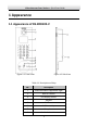
Video Intercom Door Station·Quick Start Guide 1 Appearance 1.1 Appearance of DS-KD8102-V Figure 1-1 Front View Figure 1-2 Side View Table 1-1 Descriptions of Keys No.
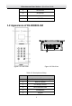
Video Intercom Door Station·Quick Start Guide 9 IR Emission 10 IR Receiver 11 Loudspeaker 12 TAMPER 1.2 Appearance of DS-KD8002-VM 10 Figure 1-3 Front View Figure 1-4 Side View Table 1-2 Descriptions of Keys No.
Video Intercom Door Station·Quick Start Guide 7 Call Button 8 Microphone 9 Call Center Key 10 TAMPER 1.3 Appearance of DS-KD3002-VM Figure 1-5 Front View Figure 1-6 Rear View Table 1-3 Descriptions Keys No.
Video Intercom Door Station·Quick Start Guide No.
Video Intercom Door Station·Quick Start Guide 2 Terminal and Wiring 2.1 Terminal Description 2.1.1 Terminals and Interfaces of DS-KD8102-V/ DS-KD8002-VM Figure 2-1 Terminals and Interfaces of DS-KD8102-V/DS-KD8002-VM Table 2-1 Descriptions of Terminals and Interfaces Name No.
Video Intercom Door Station·Quick Start Guide Name ALARM OUT ALARM IN DOOR RS485 SENSOR No.
Video Intercom Door Station·Quick Start Guide 2.1.2 Terminals and Interfaces of DS-KD3002-VM Figure 2-2 Terminals and Interfaces of DS-KD3002-VM Table 2-2 Descriptions of Terminals and Interfaces Name No.
Video Intercom Door Station·Quick Start Guide Name OUT DEBUG DOOR RS485 ALARM IN No. Interface B2 AO2+ Description B3 AO1- B4 AO1+ B5 GND Grounding B6 RX Serial Port Debugging/Receive data B7 TX Serial Port Debugging/Send data B8 3.
Video Intercom Door Station·Quick Start Guide 2.2 Wiring Description 2.2.1 Door Lock Wiring Figure 2-3 Door Lock Wiring Terminal NC1/COM1 is set as default for accessing magnetic lock/electric bolt; terminal NO1/COM1 is set as default for accessing electric strike. To connect electric lock in terminal NO2/COM2/NC2, it is required to set the output of terminal NO2/COM2/NC2 to be electric lock with Batch Configuration Tool or iVMS-4200. 2.2.
Video Intercom Door Station·Quick Start Guide Figure 2-4 Door Magnetic Wiring for DS-KD8102-V/DS-KD8002-VM (1) To connect the door magnetic, it is required to set the output of terminal AI2 to be door magnetic with Batch Configuration Tool or iVMS-4200. Figure 2-5 Door Magnetic Wiring for DS-KD8102-V/DS-KD8002-VM (2) Terminal S2 is set as default for connecting door magnetic.
Video Intercom Door Station·Quick Start Guide Door Magnetic Wiring for DS-KD3002-VM Figure 2-6 Door Magnetic Wiring for DS-KD3002-VM To connect the door magnetic, it is required to set the output of terminal AI2 to be door magnetic with Batch Configuration Tool or iVMS-4200. 2.2.3 Exit Button Wiring Exit Button Wiring for DS-KD8102-V/DS-KD8002-VM For DS-KD8102-V/DS-KD8002-VM, there are two optional ways of exit button wiring.
Video Intercom Door Station·Quick Start Guide Figure 2-8 Exit Button Wiring for DS-KD8102-V/DS-KD8002-VM (2) Exit Button Wiring for DS-KD3002-VM Figure 2-9 Exit Button Wiring for DS-KD3002-VM Terminal S1 is set as default for connecting exit button. 2.2.4 External Card Reader Wiring Please set the DIP switch first before connecting the card reader.
Video Intercom Door Station·Quick Start Guide If the DIP switch should be configured when the card reader is power-on, please reboot the card reader after configuring the DIP switch. The DIP switch description is shown in the following table: No. 1-4 Description How to Configure Set the RS-485 address ON: 1 OFF: 0 6 Select Wiegand protocol or RS-485 protocol ON: Wiegand OFF: RS-485 7 Set the Wiegand protocol (It is invalid when setting OFF in 6.
Video Intercom Door Station·Quick Start Guide Wiegand Card Reader Wiring Figure 2-11 External Card Reader Wiring 2.2.5 External Elevator Controller Wiring You can connect the door station to the elevator controller via RS-485 interface. There are 4 groups of RS-485 interfaces on the elevator controller: group A, group B, Group C, and Group D. Group C is used to connect to the door station.
Video Intercom Door Station·Quick Start Guide 2.2.
Video Intercom Door Station·Quick Start Guide 2.2.
Video Intercom Door Station·Quick Start Guide 3 Installation Before you start: Make sure the device in the package is in good condition and all the assembly parts are included. The power supply the door station supports is 12 VDC. Please make sure your power supply matches your door station. Make sure all the related equipment is power-off during the installation. Check the product specification for the installation environment. 3.
Video Intercom Door Station·Quick Start Guide The dimension of gang box for model DS-KD8102-V door station is: 404 (length)×123 (width)×47.5 (depth) mm. The dimensions above are for reference only. The actual size can be slightly different from the theoretical dimension. 3.1.2 Wall Mounting with Gang Box of DS-KD8102-V Steps: 1. Chisel a hole in the wall for inserting the gang box. The size of the hole should be larger than that of the gang box. The suggested size of hole is 404.5 (length) × 123.
Video Intercom Door Station·Quick Start Guide Figure 3-4 Install the Door Station 5. Pull the door station downward and then push it towards the inside to make sure it fits the hole. 6. Tighten the screws of the door station with the Allen wrench.
Video Intercom Door Station·Quick Start Guide 3.2 Installation of DS-KD8002-VM 3.2.1 Gang Box for DS-KD8002-VM 135 407.5 7.6 Figure 3-6 Front View 9 9 Figure 3-7 Overhead (Plan) View The dimension of gang box for model DS-KD8002-VM door station is: 407.5 mm × 135 mm × 55 mm. The dimensions above are for reference only. The actual size can be slightly larger than the theoretical dimension. 3.2.2 Wall Mounting with Gang Box of DS-KD8002-VM 1. Chisel a hole in the wall for inserting the gang box.
Video Intercom Door Station·Quick Start Guide 8.75 118 8.75 408 384 135.5 55 Figure 3-8 Dimensions of the Hole 2. Insert the gang box into the hole and fix it with 4 PA4 screws. Figure 3-9 Insert the Gang Box into the Wall 3. Make sure the edges of the gang box align to the wall and the hook A and hook B of the gang box hook onto the wall. 4. Route the cables of the door station through the cable hole. 5.
Video Intercom Door Station·Quick Start Guide Figure 3-10 Install the Door Station 7. After fixing the door station onto the gang box, secure it by inserting the plate and insert 2 POM2 screws.
Video Intercom Door Station·Quick Start Guide 3.3 Installation of DS-KD3002-VM 3.3.1 Gang Box for DS-KD3002-VM Figure 3-12 Front and Side View The dimension of gang box for model DS-KD3002-VM door station is: 343(length)× 113(width)×55(depth) mm. The dimensions above are for reference only. The actual size can be slightly different from the theoretical dimension. 3.3.2 Wall Mounting with Gang Box of DS-KD3002-VM Steps: 1. Chisel a hole in the wall for inserting the gang box.
Video Intercom Door Station·Quick Start Guide Screw Screw Figure 3-13 Insert the Gang Box into the Wall 3. Make sure the edges of the gang box align to the wall. 4. Route the cables of the door station through the cable hole. 5. Put the door station into the gang box. Figure 3-14 Install the Door Station 6. Fix the door station to the gang box with 4 crews.
Video Intercom Door Station·Quick Start Guide Figure 3-15 Tighten the Screws of Device 25
Video Intercom Door Station·Quick Start Guide 4 Local Operation 4.1 Keys Description Key descriptions of door stations are illustrated in Table 4-1. Table 4-1 Key Descriptions Key Description Numeric Key 2 ▲ Numeric Key 4 ▼ Numeric Key 6 ◄ Numeric Key 8 ► Call Key (When calling residents or center) # Confirm Return * Delete 4.2 Activate Device You cannot use the door station until you activate it. Steps: 1. Power on the door station to enter the activation interface automatically.
Video Intercom Door Station·Quick Start Guide Figure 4-2 Set Password 3. Enter a new password, and confirm the password. The character description for each numeric key is shown in Table 4-2. Table 4-2 Character Description Key Description Key Description 1 1,.
Video Intercom Door Station·Quick Start Guide 4.3 Edit Network Parameters Purpose: Network connection is mandatory for the use of door station. Steps: 1. Go to the configuration mode. 1) Hold down the * key and the # key for 2s to enter the admin password interface. 2) Enter the admin password, and press the # key. Figure 4-3 Admin Password Interface The default admin password is 888999. 2. Enter the network parameters settings interface.
Video Intercom Door Station·Quick Start Guide Figure 4-5 Network Parameters Settings Interface (private SIP) With the standard SIP protocol, you should set IP address, sub mask, gateway, and center IP. Figure 4-6 Network Parameters Settings Interface (standard SIP) 3. Edit network parameters. 1) Move the cursor to parameters to be configured. 2) Press the # key to enter or exit the editing mode. 4. Press the * key to exit the network configuration interface. 4.
Video Intercom Door Station·Quick Start Guide The default configuration password is 888999. We recommend you reset your password regularly, especially in the high security system, resetting the password monthly or weekly can better protect your product. Steps: 1. Go to the configuration mode. 1) Hold down the * key and the # key for 2s to enter the admin password interface. 2) Enter the admin password, and press the # key. Figure 4-7 Admin Password Interface The default admin password is 888999. 2.
Video Intercom Door Station·Quick Start Guide Figure 4-9 Configuration Password Changing Interface 2. Enter the old password, and the new password, and confirm the new one. 1) Move the cursor to parameters to be configured. 2) Press the # key to enter or exit the editing mode. 3. Press the * key to exit the password settings interface. Change Card Activation Password Steps: 1. On the password settings interface, press the numeric key 2 to enter the card activation password changing interface.
Video Intercom Door Station·Quick Start Guide Work as Main/Sub Door Station Steps: 1. Enter the calling No. With the private SIP protocol, the calling No. should be the room No. of the indoor station. With the standard SIP protocol, the calling No. should be the VoIP phone No. of the indoor station. And you must make sure that the indoor station supports the standard SIP protocol. 2. Press the # key or the key to start calling the resident. Work as Outer Door Station Steps: 1. Enter the calling No.
Video Intercom Door Station·Quick Start Guide The default unlocking password is 123456. Unlock Door by Card Before you start: Make sure the card has been issued. You can issue the card via the door station, or via iVMS-4200 client software. Please refer to User Manual for detail steps. Unlocking the door by swiping the card is available both in the network intercom system and the analog intercom system. Steps: Swipe the card on the card induction area to unlock the door.
Video Intercom Door Station·Quick Start Guide Appendix Installation Notice While installing the indoor station, make sure that the distance between any two devices is far enough to avoid the howling and echo. The distance between two devices is recommended to be longer than 10 meters. Here devices refer to indoor station, outdoor station and master station. Wiring Cables Cable Specification Power Cord of Door Station RVV 2*1.
Video Intercom Door Station·Quick Start Guide 35 UD09725B