Module Door Station Configuration Guide
Module Door Station Configuration Guide Legal Information User Manual ©2019 Hangzhou Hikvision Digital Technology Co., Ltd. About this Manual This Manual is subject to domestic and international copyright protection. Hangzhou Hikvision Digital Technology Co., Ltd. ("Hikvision") reserves all rights to this manual. This manual cannot be reproduced, changed, translated, or distributed, partially or wholly, by any means, without the prior written permission of Hikvision.
Module Door Station Configuration Guide TAKE ANY RESPONSIBILITIES FOR ABNORMAL OPERATION, PRIVACY LEAKAGE OR OTHER DAMAGES RESULTING FROM CYBER ATTACK, HACKER ATTACK, VIRUS INSPECTION, OR OTHER INTERNET SECURITY RISKS; HOWEVER, HIKVISION WILL PROVIDE TIMELY TECHNICAL SUPPORT IF REQUIRED. SURVEILLANCE LAWS VARY BY JURISDICTION. PLEASE CHECK ALL RELEVANT LAWS IN YOUR JURISDICTION BEFORE USING THIS PRODUCT IN ORDER TO ENSURE THAT YOUR USE CONFORMS THE APPLICABLE LAW.
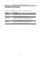
Module Door Station Configuration Guide Symbol Conventions The symbols that may be found in this document are defined as follows. Symbol Danger Caution Note Description Indicates a hazardous situation which, if not avoided, will or could result in death or serious injury. Indicates a potentially hazardous situation which, if not avoided, could result in equipment damage, data loss, performance degradation, or unexpected results.
Module Door Station Configuration Guide Regulatory Information FCC Information Please take attention that changes or modification not expressly approved by the party responsible for compliance could void the user’s authority to operate the equipment. FCC compliance: This equipment has been tested and found to comply with the limits for a Class B digital device, pursuant to part 15 of the FCC Rules.
Module Door Station Configuration Guide EU Conformity Statement This product and - if applicable - the supplied accessories too are marked with "CE" and comply therefore with the applicable harmonized European standards listed under the EMC Directive 2014/30/EU, the RoHS Directive 2011/65/EU 2012/19/EU (WEEE directive): Products marked with this symbol cannot be disposed of as unsorted municipal waste in the European Union.
Module Door Station Configuration Guide Contents 1 Device Configuration .................................................................................. 1 1.1 Activate Device .................................................................................................. 1 1.2 Edit Network Parameters .................................................................................. 2 1.3 Add Device ........................................................................................................
Module Door Station Configuration Guide 1.8 Person and Card Management ........................................................................ 21 1.8.1 Organization Management ..................................................................... 22 1.8.2 Person Management .............................................................................. 23 1.9 Video Display ................................................................................................... 32 1.9.1 Video Parameters ............
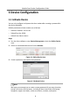
Module Door Station Configuration Guide 1 Device Configuration 1.1 Activate Device You can only configure and operate the door station after creating a password for the device activation. Default parameters of door station are as follows: • Default IP Address: 192.0.0.65. • Default Port No.: 8000. • Default User Name: admin. Steps 1. Run the client software, enter Device Management, check the Online Device area. 2. Select an inactivated device and click the Activate. Figure 1-1 Online Device Area 3.
Module Door Station Configuration Guide characters) in order to increase the security of your product. And we recommend you reset your password regularly, especially in the high security system, resetting the password monthly or weekly can better protect your product. 4. Click OK to activate the device. Note • When the device is not activated, the basic operation and remote operation of device cannot be performed.
Module Door Station Configuration Guide Figure 1-4 Modify Parameters Note • The default port No. is 8000. • The default IP address of the door station is 192.0.0.65. • After editing the network parameters of device, you should add the devices to the device list again. 1.3 Add Device To configure the device remotely, you need to add the device to iVMS-4200 client software. Steps 1. Select the activated device and click Add to Client. Figure 1-5 Add Device 2.
Module Door Station Configuration Guide Figure 1-6 Add to the Client 1.4 Reset Password You can restore the default password or resetting the password for the door station. Steps 1. Select the device from the online device list, click Reset Password. If the window with import file button, key importing mode drop-down list, password and confirm password field pops up. 2. Click Export to save the device file on your computer. 3. Send the file to our technical engineers. 4.
Module Door Station Configuration Guide characters) in order to increase the security of your product. And we recommend you reset your password regularly, especially in the high security system, resetting the password monthly or weekly can better protect your product. 1.5 System Click System on the remote configuration page to display the device information: Device Information, General, Time, System Maintenance, User, and RS-485.
Module Door Station Configuration Guide Time Click Time to enter the device time settings page. Figure 1-9 Synchronize Time Select Time Zone or Enable NTP. Click Save to save the time settings. • • • Time Zone - Select a time zone from the drop-down list menu. - Click the Synchronization. NTP - Check the checkbox of Enable NTP to enable NTP. - Enter the server address, NTP port, and synchronization interval. DST - Check the checkbox of Enable DST to enable DST.
Module Door Station Configuration Guide Figure 1-10 System Maintenance • Click Reboot and the system reboot dialog box pops up. Click Yes to reboot the system. • Click Restore Default Settings to restore the default parameters. • Click Restore All to restore all parameters of device and reset the device to inactive status. Note • - Click Restore Default Settings, all default settings, excluding network parameters, will be restored.
Module Door Station Configuration Guide • Click Export Configuration File and the export file window pops up. Select the saving path of remote configuration files and click Save to export the configuration file. • Click ... to select the upgrade file and click Upgrade to remote upgrade the device. The process of remote upgrade will be displayed in the process bar. • Select a language, and click Save to change the device system language.
Module Door Station Configuration Guide Note • The new password and confirm password should be identical. • After editing the password of device, click refresh button from the device list, the added device will not be there. You should add the device again with new password to operate the remote configuration. RS-485 Click RS485 to enter the RS-485 settings page. You can view and edit the RS-485 parameters of the device.
Module Door Station Configuration Guide Steps 1. Click ID Configuration to enter the device ID configuration page. Figure 1-13 Device No. Configuration 2. Select the device type from the drop-down list, and set the corresponding information. 3. Click Save to enable the device number configuration. Note • For main door station, the serial No. is 0. • For sub door station, the serial No. is higher than 0. Serial No. ranges from 1 to 99.
Module Door Station Configuration Guide 2. Configure the maximum ring duration, maximum live view time, and call forwarding time. 3. Click Save. Note For door station, maximum speaking time and maximum message time should be configured. Maximum speaking time varies from 90 s to 120 s, and maximum message time varies from 30 s to 60 s. 1.6.3 Permission Password Steps 1. Click Permission Password to enter the permission password page. Figure 1-15 Permission Password 2. Edit the password accordingly. 3.
Module Door Station Configuration Guide Steps 1. Click Access Control and Elevator to enter corresponding configuration page. Figure 1-16 Access Control and Elevator 2. Set the Access Control parameters. 1) Select the door No. 2) Set the Door-unlocked Duration. 3) Optional: Enable Upload Alarm for Not-Closed Door. 4) Click Save to enable the settings. Note • The door-unlocked duration ranges from 1 s to 255 s.
Module Door Station Configuration Guide 3) Select network interface as interface type. Enter the elevator controller's IP address, port No., user name, and password. 4) Enable the elevator control. Note • Up to 4 elevator controllers can be connected to one door station. • Up to 10 negative floors can be added. • Make sure the interface types of elevator controllers, which are connected to the same door station, are consistent. 1.6.5 I/O Input and Output Steps 1.
Module Door Station Configuration Guide Steps 1. Click Volume Input/Output to enter the volume input and output page. Figure 1-18 Volume Input and Output 2. Slide the slider to adjust the volume input, volume output, and talk volume. 3. Click Save to enable the settings. 1.6.7 Dial Steps 1. Click Dial to enter the dial page.
Module Door Station Configuration Guide Figure 1-20 Dial (Standard SIP) 2. Enter the room No. of the indoor station that the door station connected to. 3. Click Save to enable the settings. Note By default, quick press the call button, the door station calls resident. If you check Quick Press for Calling Center, the door station calls the management center when quick press the call button of the main unit. 1.6.8 Motion Detection Steps 1. Click Motion Detection to enter the motion detection page.
Module Door Station Configuration Guide 2. Enable Enable Motion Detection. 3. Configure the parameters. 4. Click Save. Note The arming schedule is defaulted as all-day. 1.6.9 Intercom Protocol Steps 1. Click Intercom Protocol to enter the intercom protocol page. 2. Select the protocol according to needs. 3. Click Save. 1.6.10 Sub Module Steps 1. Click Sub Module to enter the sub module configuration page. Figure 1-22 Sub Module 2. Optional: Enter the Room No. for each call button of the nametag module.
Module Door Station Configuration Guide 3. Click Save. Note • The module address is used to differentiate the sub modules. See Configure Sub Module Address for detailed configuration instructions. • For the other sub modules (indicator module, keypad module, display module and card reader module), it prompts Not supported. • The room No. for the main unit's call button is 1 by default; and the room No. for the nametag modules call buttons are 2 to 7 by default.
Module Door Station Configuration Guide 1.7.1 Local Network Configuration Steps 1. Click Local Network Configuration to enter local network configuration page. Figure 1-24 Local Network Configuration 2. Enter the Local IP Address, Subnet Mask, Default Gateway, Port and HTTP Port. 3. Click Save to enable the settings. Note • The default port No. is 8000. • After editing the local network parameters of device, you should add the devices to the device list again. 1.7.
Module Door Station Configuration Guide Figure 1-25 Linked Device Network 2. Enter the Master Station IP Adderss, (Main) Door Station IP Address, SIP Server IP Address, Security Control Panel IP Address and Port No. 3. Select the main door station type from the drop-down list. 4. Click Save to enbale the settings. Note • After adding master station IP Address, the linkage between indoor station and master station can be realized.
Module Door Station Configuration Guide Figure 1-26 FTP Settings 2. Enable Enable Main FTP. 3. Select IP address from the drop-down list of server mode. 4. Enter the FTP server address, and port No. 5. Optional: Enable the anonymity. 6. Enter the name and password. 7. Select the directory structure and set the separator, naming item, and naming element. 8. Click Save to enable the settings. Note • The default port No. is 21.
Module Door Station Configuration Guide Figure 1-27 Advanced Settings 2. Enter the DNS server addresses. 3. Click Save to enable the settings. 1.8 Person and Card Management You can add, edit, and delete the organization and person in Person and Card Management module. Organization and person management is necessary for the video intercom function. For the first time opening the Access Control module, the following dialog will pop up and you are required to select the scene according to the actual needs.
Module Door Station Configuration Guide Figure 1-29 Person and Card Management The page is divided into two parts: Organization Management and Person Management. Organization Management You can add, edit, or delete the organization as desired. Person Management After adding the organization, you can add the person to the organization and issue card to persons for further management. 1.8.1 Organization Management Add Organization Steps 1.
Module Door Station Configuration Guide Note Up to 10 levels of organizations can be created. Modify and Delete Organization You can select the added organization and click Modify to modify its name. You can select an organization, and click Delete button to delete it. Note • The lower-level organizations will be deleted as well if you delete an organization. • Make sure there is no person added under the organization, or the organization cannot be deleted. 1.8.
Module Door Station Configuration Guide 2) Optional: Click Upload Picture to select the person picture from the local PC to upload it to the client. Note The picture should be in *.jpg format. 3) Optional: You can also click Take Phone to take the person's photo with the PC camera. 3. Set linked device for the person. 1) Click Details. Figure 1-30 Details 2) Set the linked devices. Linked Device You can bind the indoor station to the person.
Module Door Station Configuration Guide Figure 1-31 Issue Card 2) Click Add to pop up the Add Card dialog.
Module Door Station Configuration Guide Figure 1-32 Add Card 3) Select Normal Card. 4) Enter the password of the card itself in the Card Password field. The card password should contain 4 to 8 digits. 5) Enter Card Number manually. 6) Click OK and the card(s) will be issued to the person. Import and Export Person Information The person information can be imported and exported in batch. Steps 1. Exporting Person: You can export the added persons' information in Excel format to the local PC.
Module Door Station Configuration Guide 1) After adding the person, you can click Export Person to pop up the following dialog. 2) Click ... to select the path of saving the exported Excel file. 3) Check the checkboxes to select the person information to export. Figure 1-33 Export Person 4) Click OK to start exporting. 2. Importing Person: You can import the Excel file with persons information in batch from the local PC. 1) Click Import Person.
Module Door Station Configuration Guide Get Person Information from Device If the added device has been configured with person information (including person details, fingerprint, issued card information), you can get the person information from the device and import to the client for further operation. Steps Note This function is only supported by the device the connection mothod of which is TCP/IP when adding the device. 1.
Module Door Station Configuration Guide Note • The person information, including person details, person's fingerprint information (if configured), and the linked card (if configured), will be imported to the selected organization. • If the person name stored in the device is empty, the person name will be filled with the issued card No. after importing to the client. • The gender of the persons will be Male by default.
Module Door Station Configuration Guide Steps • For one person, you can add up to 4 access groups to one access control point of one device. • You can add up to 128 access groups in total. • When the access group settings are changed, you need to apply the access groups to the devices again to take effect.
Module Door Station Configuration Guide Caution • Be careful to click Apply All to Devices, since this operation will clear all the access groups of the selected devices and then apply the new access group, which may brings risk to the devices. • You can click Apply Changes to Devices to only apply the changed part of the selected access group(s) to the device(s). 3) View the apply status in the Status column or click Applying Statusto view all the applied access group(s).
Module Door Station Configuration Guide Figure 1-36 Issue Card in Batch 2. Select Normal Card as Card Type. 3. Enter the card quantity issued for each person. 4. Select the card reader mode and fill related information. 5. Click Read/Enter. 6. After issuing the card to the person, the person and card information will display in the Person(s) with Card Issued list. 7. Click OK. 1.9 Video Display 1.9.1 Video Parameters Steps 1. Click Video Parameters to enter the video parameters settings page.
Module Door Station Configuration Guide Figure 1-37 Video Parameters 2. Select the Camera No. 3. Select the video standard (PAL and NTSC can be selected). 4. Optional: Enable WDR mode. 5. Set the Brightness, Contrast, Saturation and Sharpness of the video. 6. Click Save. Note Click Restore Default Settings to restore all video parameters excluding network parameters to the factory settings. 1.9.2 Video & Audio Steps 1. Click Video & Audio to enter the video parameters settings page.
Module Door Station Configuration Guide Figure 1-38 Video & Audio 2. Set the parameters. 3. Click Save. Note It's suggested to keep the default settings to ensure the video/image quality. 1.10 BLC Mode Steps 1. Click Back Light Compensation to enter the settings page. Figure 1-39 BLC Mode 2. Set the BLC Mode. 3. Click Save.
Module Door Station Configuration Guide 2 Video Intercom Operation 2.1 Video Intercom Operation via Device 2.1.1 Call Resident Note • Make sure you have configured the room No. of the device. • Make sure you have add contacts to the device via iVMS-4200 Client Software. You can call corresponding resident in three ways: • Press the call button on the main unit or on the nametag unit. • Enter the Room No. on the keypad module, and press # to start calling. Note You can press * to hang up.
Module Door Station Configuration Guide 2.1.3 Unlock Door Unlock Door by Password You can unlock the door by inputting the password via the keypad module. Three formats of password are supported. They are: • 【#】+ Public Password +【#】 • 【#】+ Room No. + Password +【#】 • 【#】+ Room No. + Duress Password +【#】 Note • Password contains 6 digits. • You're allowed to set 3 public passwords via iVMS-4200 client software. • The password varies according to different rooms.
Module Door Station Configuration Guide You should add the device to the software and configure the person to link the device in Access Control module before your configuration remotely. Click → on the left icon bar to enter the Video Intercom page. 2.2.1 Receive Call from Door Station Steps 1. Select the client software in door station page to start calling the client and an incoming call dialog will pop up in the client software. Figure 2-1 Device Call 2. Click Answer to answer the call.
Module Door Station Configuration Guide Note • One video intercom device can only connect with one client software. • The maximum ring duration can be set from 15s to 60s via the Remote Configuration of the video intercom device. • The maximum speaking duration between indoor station and iVMS-4200 can be set from 120s to 600s via the Remote Configuration of indoor station.
Module Door Station Configuration Guide Steps 1. In the Video Intercom page, click Call Log to enter the Call Log page. Figure 2-3 View Call Logs All the call logs will display on this page and you can check the log information, e.g., call status, start time, resident's organization and name, device name and ring or speaking duration. 2. Optional: Click the call button to re-dial the resident. 3. Optional: Click the cancel button to delete the call log. Or you can click Clear to delete all logs. 2.2.
Module Door Station Configuration Guide Figure 2-4 Call Logs 2. Set the search conditions, including call status, device type, start time and end time. Call Status Click ˅to unfold the drop-down list and select the call status as Dialed, Received or Missed. Or select All to search logs with all statuses. Device Type Click ˅ to unfold the drop-down list and select the device type as Indoor Station, Door Station, Outer Door Station or Analog Indoor Station.
Module Door Station Configuration Guide Steps 1. In the Information Search page, click Unlocking Log to enter the Unlocking Log page. Figure 2-5 Unlocking Logs 2. Set the search conditions, including unlocking type, device type, start time and end time. Unlocking Type Click ˅ to unfold the drop-down list and select the unlocking type as Unlock by Password, Unlock by Duress, Unlock by Card, Unlock by Resident or Unlock by Center. Or select All to search logs with all unlocking types.
Module Door Station Configuration Guide 6. Optional: Click on the Capture column to view the captured pictures. Note Viewing captured picture should be supported by device. 7. Optional: Click Export to export the unlocking logs to your PC.
UD14533B