
User Manual
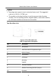
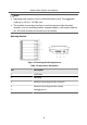
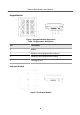
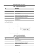
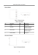
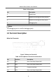
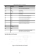
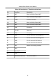
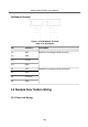
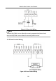
Table Of Contents
- Legal Information
- Symbol Conventions
- Regulatory Information
- 1 Terminal and Wiring
- 2 Installation
- 3 Activation
- 4 Remote Configuration via Web
- 4.1 Live View
- 4.2 User Management
- 4.3 Number Settings
- 4.4 Device Management
- 4.5 Parameters Settings
- 5 Configuration via Client Software
- A. Communication Matrix and Device Command

Table 1-8 Descripon
No. Descripon
1 Display Area
2 Module-connecng Interface (output)
3 Module-connecng Interface (input)
4 Debugging Port
Note
The debugging port is used for debugging only.
1.2 Terminal Descripon
Main Unit Terminals
Figure 1-9 Main Unit Terminals
Table 1-9 Descripons of Terminals and Interfaces
No. Interface Descripon
A1 NC1 Door Lock Relay Output (NC)
A2 NO1 Door Lock Relay Output (NO)
A3 COM Common Interface
A4 NC2 Door Lock Relay Output (NC)
Module Door Staon User Manual
7