
User Manual
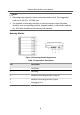
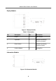
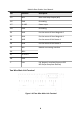
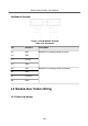
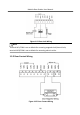
Table Of Contents
- Legal Information
- Symbol Conventions
- Regulatory Information
- 1 Terminal and Wiring
- 2 Installation
- 3 Activation
- 4 Remote Configuration via Web
- 4.1 Live View
- 4.2 User Management
- 4.3 Number Settings
- 4.4 Device Management
- 4.5 Parameters Settings
- 5 Configuration via Client Software
- A. Communication Matrix and Device Command

No. Interface Descripon
A5 NO2 Door Lock Relay Output (NO)
A6 GND Grounding
A7 12 VDC Power Input
A8 GND Grounding
B1 AIN2 For the access of Door Magnec 2
B2 AIN1 For the access of Door Magnec 1
B3 AIN3 For the access of Exit Buon 1
B4 AIN4 For the access of Exit Buon 2
B5 485- Module-connecng Interface
B6 485+
B7 12 V OUT
B8 GND
C LAN PoE Network Interface(Supports IEEE
802.3af/at-Compliant Devices)
Two-Wire Main Unit Terminal
Figure 1-10 Two-Wire Main Unit Terminal
Module Door Staon User Manual
8