
User Manual
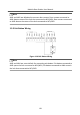
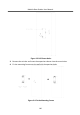
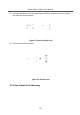
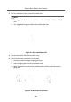
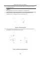
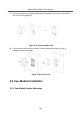
Table Of Contents
- Legal Information
- Symbol Conventions
- Regulatory Information
- 1 Terminal and Wiring
- 2 Installation
- 3 Activation
- 4 Remote Configuration via Web
- 4.1 Live View
- 4.2 User Management
- 4.3 Number Settings
- 4.4 Device Management
- 4.5 Parameters Settings
- 5 Configuration via Client Software
- A. Communication Matrix and Device Command

2 Installaon
Note
•
Make sure the device in the package is in good condion and all the assembly
parts are included.
•
Sub module must work along with the main unit.
•
Set the sub module address before start the installaon steps.
•
Make sure the place for surface
mounng is at.
•
Make sure all the related equipment is power-o during the installaon.
•
Tools that you need to prepare for installaon:
Drill (ø6), cross screwdriver (PH1*150 mm), and gradienter.
2.1 Congure Sub Module Address
You need to set the sub module address via DIP switch before installaon.
Steps
1.
Remove the rubber cover on the rear panel of the sub module to expose the DIP
switch.
Figure 2-1 DIP Switch
2.
Set the sub module address according to the DIP rules, and install the rubber
cover back.
Module Door
Staon User Manual
13