
User Manual
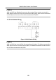
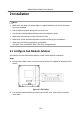
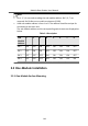
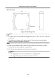
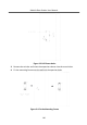
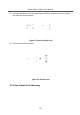
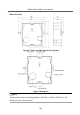
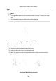
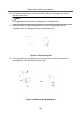
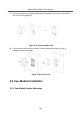
Table Of Contents
- Legal Information
- Symbol Conventions
- Regulatory Information
- 1 Terminal and Wiring
- 2 Installation
- 3 Activation
- 4 Remote Configuration via Web
- 4.1 Live View
- 4.2 User Management
- 4.3 Number Settings
- 4.4 Device Management
- 4.5 Parameters Settings
- 5 Configuration via Client Software
- A. Communication Matrix and Device Command

Note
•
Bit 1, 2, 3, 4 are used to coding the sub module address. Bit 5, 6, 7 are
reserved. Set Bit 8 as on to enable a resistance (120Ω).
•
Valid sub module address is from 1 to 8. The address should be unique for
connecng to the main unit.
The sub module address and its corresponding switch status are displayed as
below.
Table 2-1 Descripon
Sub
Module
Address
1 2 3 4 5 6 7 8
Bit 1 ON OFF ON OFF ON OFF ON OFF
Bit 2 OFF ON ON OFF OFF ON ON OFF
Bit 3 OFF OFF OFF ON ON ON ON OFF
Bit 4 OFF OFF OFF OFF OFF OFF OFF ON
2.2 One-Module Installaon
2.2.1 One-Module Surface Mounng
Module Door Staon User Manual
14