
User Manual
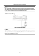
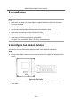
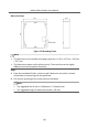
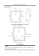
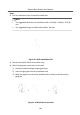
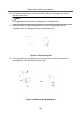
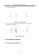
Table Of Contents
- Legal Information
- Symbol Conventions
- Regulatory Information
- 1 Terminal and Wiring
- 2 Installation
- 3 Activation
- 4 Remote Configuration via Web
- 4.1 Live View
- 4.2 User Management
- 4.3 Number Settings
- 4.4 Device Management
- 4.5 Parameters Settings
- 5 Configuration via Client Software
- A. Communication Matrix and Device Command

Before You Start
Figure 2-2 Mounng Frame
Note
•
The dimension of one module mounng frame (W × H × D) is: 117 mm × 107 mm
× 32.7 mm.
•
The dimensions above are for reference only. The actual size can be slightly
dierent from the theorecal dimension.
Steps
1.
Paste the installaon Scker 1 onto the wall. Make sure the scker is placed
horizontally via measuring with the gradienter.
2.
Drill 4 holes according to the screw holes on the scker.
Note
•
The suggested size of hole is 6 (diameter) × 25 (depth) mm.
•
The suggested length of cables le outside is 100 mm.
Module Door Staon User Manual
15