
User Manual
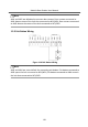
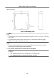
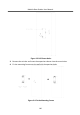
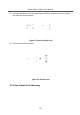
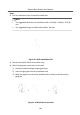
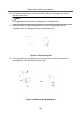
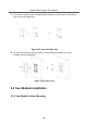
Table Of Contents
- Legal Information
- Symbol Conventions
- Regulatory Information
- 1 Terminal and Wiring
- 2 Installation
- 3 Activation
- 4 Remote Configuration via Web
- 4.1 Live View
- 4.2 User Management
- 4.3 Number Settings
- 4.4 Device Management
- 4.5 Parameters Settings
- 5 Configuration via Client Software
- A. Communication Matrix and Device Command

4.
Drill 4 holes according to marks on the wall, and insert the expansion sleeves
into the screw holes.
Note
The suggested size of the hole is 6 (diameter) × 45 (depth) mm.
5.
Route the cables through the gang box hole. Insert the gang box into the
installaon hole. Fix the gang box with 4 expansion bolts.
Figure 2-11 Fix the Gang Box
6.
Fill the gap between the gang box and the wall with concrete. Remove the 4
mounng ears with tool aer concrete is dry.
Figure 2-12 Remove the Mounng Ears
Module Door
Staon User Manual
20