
User Manual
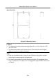
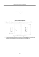
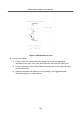
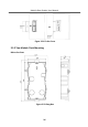
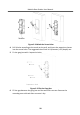
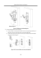
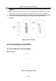
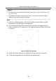
Table Of Contents
- Legal Information
- Symbol Conventions
- Regulatory Information
- 1 Terminal and Wiring
- 2 Installation
- 3 Activation
- 4 Remote Configuration via Web
- 4.1 Live View
- 4.2 User Management
- 4.3 Number Settings
- 4.4 Device Management
- 4.5 Parameters Settings
- 5 Configuration via Client Software
- A. Communication Matrix and Device Command

Figure 2-18 Placement of Lines
6.
Connect the cables.
1) Connect the lines and
module-connecng line to the corresponding
interfaces of the main unit, then place the main unit into the upper grid.
2) Connect the other end of the module-connecng line to the input interface
of the sub module.
3) Organize the cable with cable
e in the package. The suggested cable
connecon picture as shown below.
Module Door
Staon User Manual
24