
User Manual
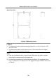
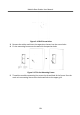
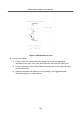
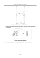
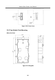
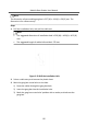
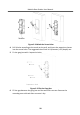
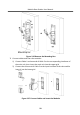
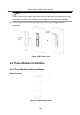
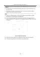
Table Of Contents
- Legal Information
- Symbol Conventions
- Regulatory Information
- 1 Terminal and Wiring
- 2 Installation
- 3 Activation
- 4 Remote Configuration via Web
- 4.1 Live View
- 4.2 User Management
- 4.3 Number Settings
- 4.4 Device Management
- 4.5 Parameters Settings
- 5 Configuration via Client Software
- A. Communication Matrix and Device Command

Note
Cable 1 refers to the cables pulled out from the wall that connected to the main
unit. Cable 2 refers to the module-connecng line in the accessory package.
8.
Fix the cover with 2 socket head cap screws by using a hexagon wrench
(supplied).
Figure 2-28 Fix the Cover
2.4 Three-Module
Installaon
2.4.1 Three-Module Surface Installaon
Before You Start
Figure 2-29 Mounng Frame
Module Door Staon User Manual
30