
User Manual
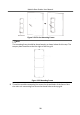
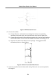
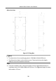
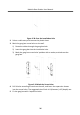
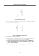
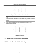
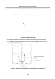
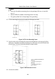
Table Of Contents
- Legal Information
- Symbol Conventions
- Regulatory Information
- 1 Terminal and Wiring
- 2 Installation
- 3 Activation
- 4 Remote Configuration via Web
- 4.1 Live View
- 4.2 User Management
- 4.3 Number Settings
- 4.4 Device Management
- 4.5 Parameters Settings
- 5 Configuration via Client Software
- A. Communication Matrix and Device Command

Figure 2-31 Fix the Mounng Frame
Note
The mounng frame should be placed exactly as shown below for this step. The
tamper plate should be at the low right of the rst grid.
Figure 2-32 Mounng Frame
5.
Thread the module-connecng line across the thread holes of the frame. Pass
the main unit connecng line across the thread hole to the top grid.
Module Door
Staon User Manual
32